
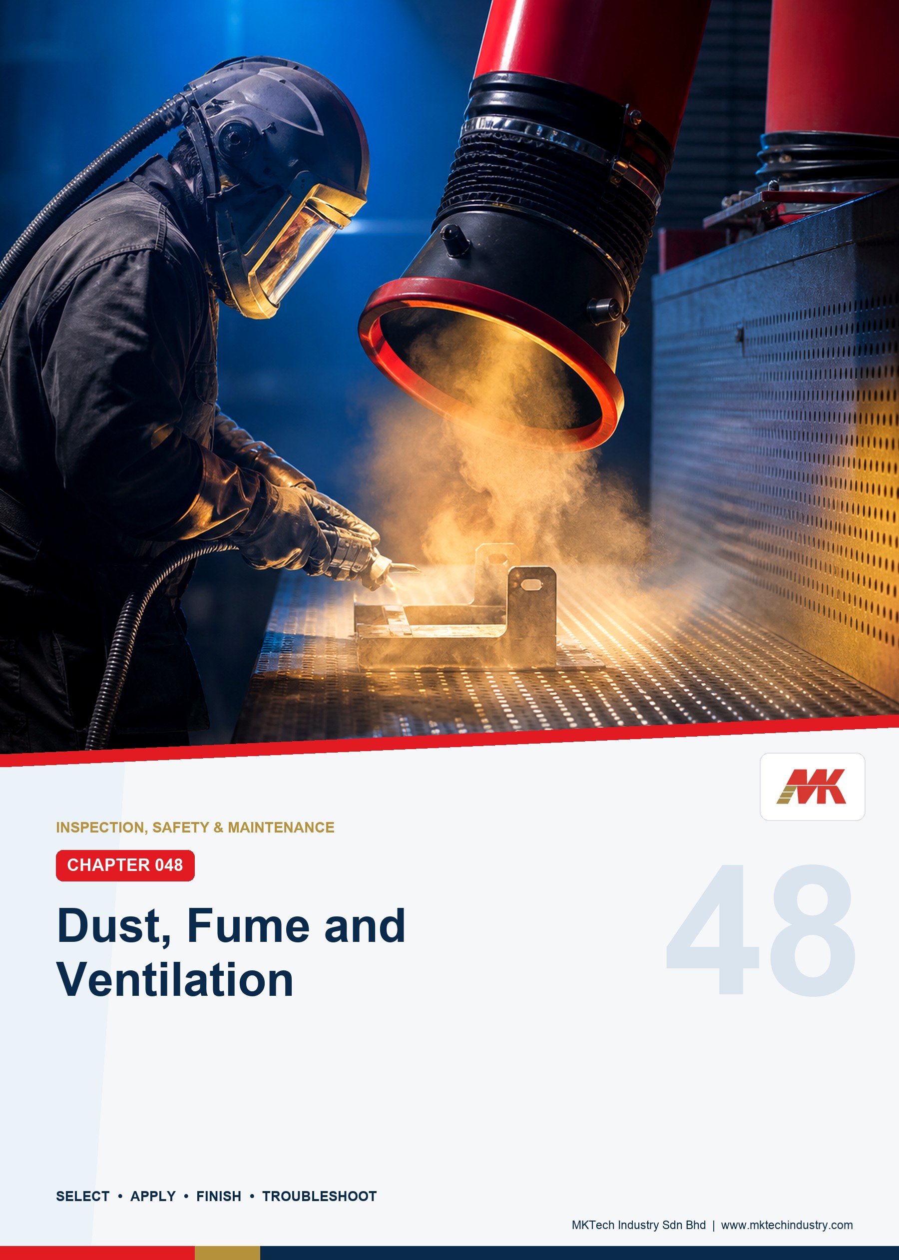
Production managers, workshop supervisors, safety and health personnel, operators, maintenance teams, technical buyers and application personnel involved in grinding, cutting, sanding, polishing, weld preparation and industrial surface finishing
Identification and control of dust, fume, mist, gas and vapour; source capture; local exhaust ventilation; wet methods; general ventilation; daily checks; maintenance; housekeeping; waste handling and troubleshooting.
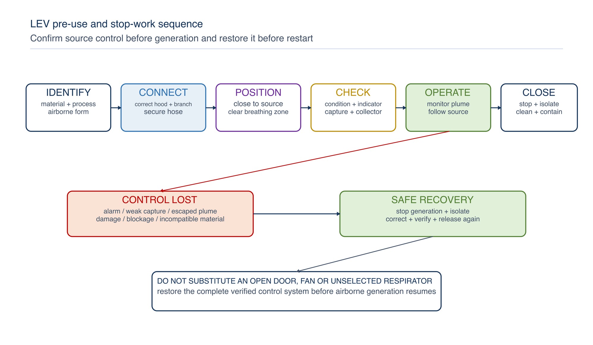
If extraction fails, stopping generation is normally the first safe response. Do not continue merely by opening a door, adding a fan or wearing an unselected respirator. Isolate hazardous energy before opening, clearing or maintaining the system. Assess chemical, confined-space, fire, explosion, sharp-object, work-at-height and manual-handling hazards before internal access or collector servicing. Move to a safe area, isolate as required, control access and report the condition. Restart only after the cause has been corrected and the complete control arrangement has passed its release checks.
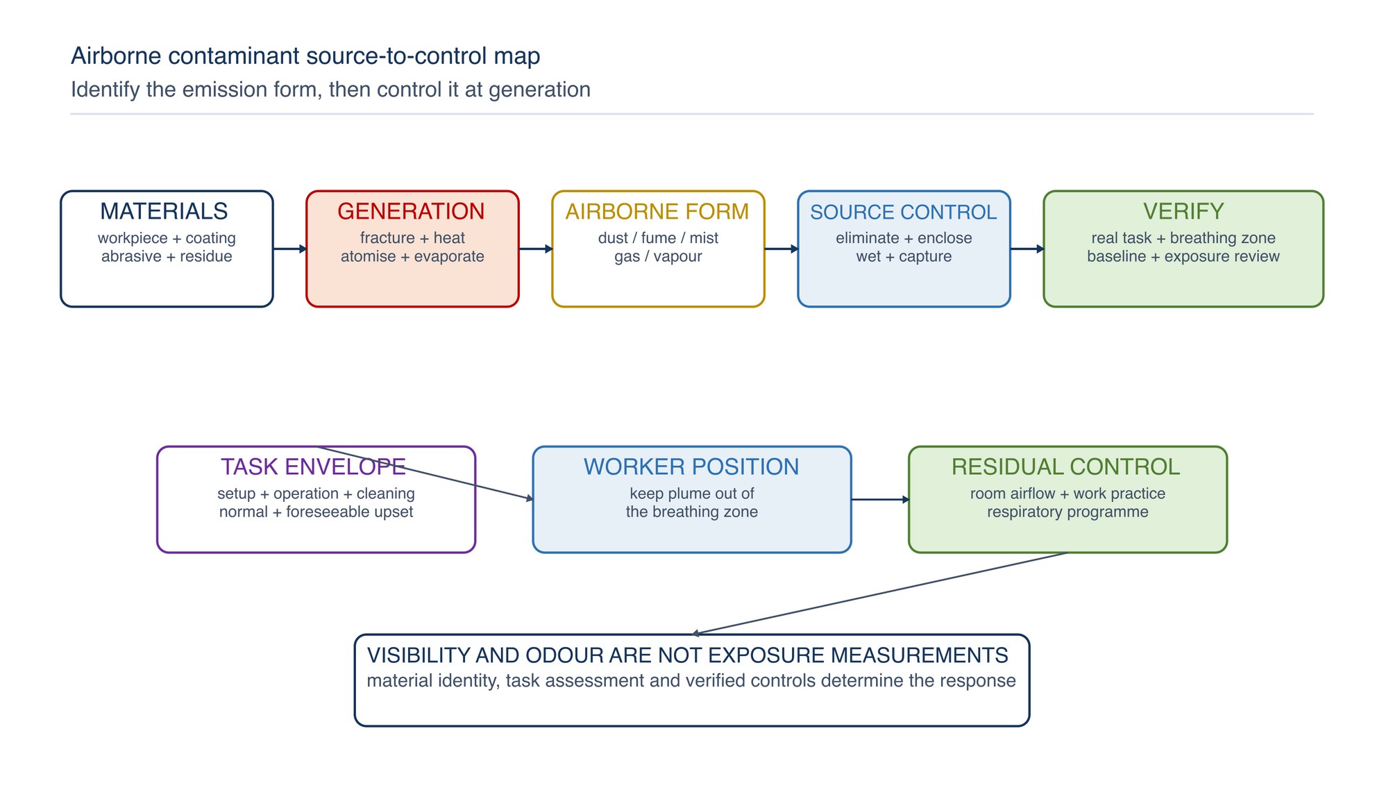
Effective airborne-contaminant control begins at the point of generation. Capture or suppress the emission before it crosses the worker's breathing zone, then verify that the complete control system remains effective during the real task.
Grinding and surface finishing can release material from the workpiece, coating, abrasive and process residue. Adjacent welding, thermal cutting, cleaning and coating work may add fume, mist, gas or vapour. The appropriate control depends on what is released, how it moves and where people stand—not simply on whether a cloud can be seen. Malaysian chemical-health requirements place engineering control ahead of personal protective equipment and require the workplace to assess and control actual exposure. [S275; S288]
Chapter objectives
After this chapter, the reader should be able to:
- distinguish dust, fume, mist, gas and vapour;
- identify the materials contributing to an airborne mixture;
- select elimination, substitution, enclosure, wet methods or local extraction in the correct order;
- distinguish source capture from general room ventilation;
- position an extraction hood relative to the source, emission direction and operator;
- explain the function of each component in an LEV system;
- recognise common causes of lost capture and poor transport;
- carry out practical pre-use checks without treating them as commissioning tests;
- coordinate extraction with make-up air, workpiece movement and neighbouring processes;
- control filter, collector and dust-disposal work;
- identify conditions that require the task to stop; and
- troubleshoot common ventilation failures systematically.
Identify what becomes airborne
Begin with every material that can enter the process. The airborne mixture may contain base metal, alloying elements, rust, scale, paint, plating, oil, adhesive, filler, abrasive grain, bond material, polishing compound or cleaning residue. Heating can change the form and chemistry of contamination. A coating that appears harmless while cold may release a different mixture when ground or heated.
| Airborne form | How it is commonly generated | Practical control implication |
|---|---|---|
| Dust | Mechanical fracture, abrasion, sanding, grinding, cutting or dry handling | Capture particle momentum close to the tool; prevent deposits and re-suspension |
| Fume | Condensation of material vaporised by welding, thermal cutting or intense heat | Capture the rising or process-driven plume close to formation without disturbing the process |
| Mist | Atomised or mechanically dispersed liquid from sprays, coolants or wet processes | Control droplets at the source and prevent contaminated liquid accumulation |
| Gas | Process reaction, combustion, decomposition or shielding-gas displacement | Identify the gas and assess ventilation, accumulation and oxygen conditions |
| Vapour | Evaporation of solvent, cleaner, coating or other volatile liquid | Prefer containment and closed handling; assess ignition and chemical hazards |
Particle size cannot be judged reliably by sight. A settling layer proves that material escaped, but the absence of visible dust does not prove acceptable air quality. Odour is equally unreliable because some hazardous substances have little warning property and sensory response varies between people.
Map the emission to the real task
Observe the complete work cycle: setup, initial contact, continuous operation, repositioning, abrasive change, cleaning and waste removal. Record where the emission starts, its direction and momentum, how the tool and workpiece move, where the operator breathes and what cross-draughts are present.
Ask:
- Which materials can contribute to the airborne mixture?
- Does the process fracture material, heat it, atomise liquid or evaporate chemicals?
- Is generation continuous, intermittent or concentrated at entry and exit?
- Does a rotating abrasive eject particles tangentially?
- Does a hot plume rise, or is it driven sideways by the process?
- Can the workpiece remain inside an enclosure or close to a hood?
- Does the operator stand between the source and the hood?
- Do doors, fans, vehicles or compressed air disturb capture?
- What happens during cleaning, filter changes and waste disposal?
The workplace chemical-risk assessment and exposure-monitoring programme determine whether control is adequate. A generic tool description, room volume or visible-dust impression cannot replace that assessment. [S288; S303]
Apply the control hierarchy at the process
Control is most dependable when generation is prevented or the source is enclosed. Consider the following sequence:
- eliminate unnecessary abrasive or chemical work;
- remove hazardous coatings or residues by a safer controlled method before hot or abrasive work;
- substitute a lower-emission material, process or product where technically suitable;
- automate, isolate or fully enclose the operation;
- use compatible wet methods or tool-integrated extraction;
- capture remaining emissions with correctly designed LEV;
- use general ventilation to manage background contamination and replacement air;
- control access, work sequence, cleaning and maintenance; and
- select respiratory protection for the residual exposure through the workplace programme.
Wet methods are not automatically suitable. Water or process fluid must be compatible with the electrical tool, abrasive product, workpiece, downstream finish, collected material and waste route. Avoid using a wet method where it creates electrical, corrosion, reaction, slip or contamination hazards. Exact product compatibility must be confirmed. Refer to the product label, Technical Data Sheet, or MKTECH representative.
Distinguish local extraction from general ventilation
Local exhaust ventilation captures contamination close to its source and conveys it away for separation and safe discharge. General ventilation supplies and removes room air to dilute background contamination and control overall air movement.
| Control | Best use | Limitation to recognise |
|---|---|---|
| Tool-integrated extraction | Mobile sanding or grinding where the extraction point follows the abrasive contact | Small passages and hoses block easily; connection and airflow must suit the complete system |
| Partial or full enclosure | Repetitive work that can remain within a controlled opening | Large openings, poor part positioning or open access reduce containment |
| Captor or receiving hood | A predictable plume or particle trajectory | Capture declines rapidly when distance increases or cross-draughts dominate |
| Downdraught or backdraught surface | Work that can be positioned over or in front of a distributed capture area | Covered or overloaded areas and poor workpiece position can short-circuit airflow |
| General room ventilation | Make-up air, background dilution and control of room airflow | Does not reliably capture concentrated emissions at the worker's breathing zone |
Using a pedestal fan to blow a cloud away from one operator may move it toward another person, an ignition source or an unprotected work area. Air movement should form part of a designed path from clean air, past the operator where appropriate, toward the capture point and safe discharge.
Capture close to the point of generation
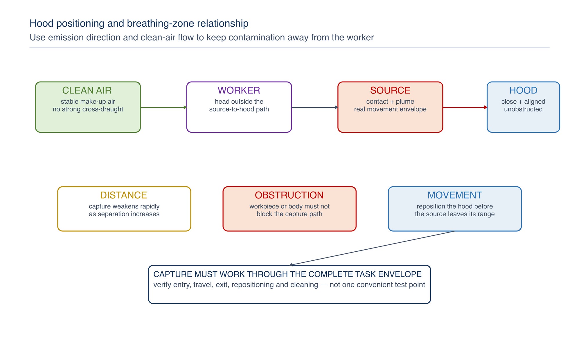
The hood is the interface between the process and the ventilation system. DOSH identifies it as the most important LEV component because it must collect the contaminant into the airflow. Hood position should account for emission direction, worker position and room airflow. [S302]
Practical positioning rules are:
- keep the capture point as close as the task safely permits;
- use the natural or process-driven movement of the contaminant;
- place the hood so contamination moves away from the breathing zone;
- minimise the open area that must be controlled;
- avoid placing large workpieces between the source and the hood;
- reposition a movable hood whenever the source moves;
- keep guards, fixtures and extraction working together; and
- do not allow a hose or hood to interfere with tool control, visibility or emergency movement.
An exterior hood must pull air across a distance and is therefore sensitive to separation and cross-draughts. Enclosing hoods use inward airflow at an opening and are generally less vulnerable when the process can be contained. A receiving hood can use the momentum of a plume or particle stream, but it must be large and correctly located for all expected directions.
Match capture to abrasive motion
Rotating tools eject material in a directional path. Extraction placed on the wrong side of the contact may collect settled debris while the airborne fraction passes the operator. Determine tool rotation, contact point, spark path, wheel or belt travel and workpiece obstruction before selecting hood position.
| Application | Preferred control concept | Positioning focus |
|---|---|---|
| Bench or pedestal grinding | Close-fitting ventilated guard or enclosure integrated with the machine | Collect near the wheel periphery and work contact without weakening the safety guard |
| Belt sanding | Enclosure and extraction at the belt contact and carry-off direction | Control both primary ejection and material carried around the belt |
| Disc or orbital sanding | Tool-integrated extraction with suitable perforated abrasive and backing system | Maintain alignment of extraction holes and an unrestricted hose path |
| Portable grinding on large work | Movable capture or partial enclosure where practicable | Reposition capture as the contact point moves; keep the operator out of the source-to-hood path |
| Polishing or buffing | Receiving or enclosing hood arranged for the wheel's throw direction | Account for lint, compound, heat and combustible deposits |
| Abrasive cutting | Enclosure or local capture compatible with guard and cut path | Do not modify the guard or create binding to improve extraction |
NIOSH work on ventilated sanders supports the principle that extraction integrated close to the sanding interface can materially reduce dust for the assessed application. That evidence does not establish performance for another tool, abrasive, material or extraction unit. [S306]
Control welding and thermal-process fume nearby
Surface preparation often occurs beside welding, gouging or thermal cutting. Treat these emissions as process-specific fume and gas hazards rather than ordinary grinding dust. ISO 21904-1 addresses equipment for capturing and separating welding fume, including hoods, ducting, filter units, air movers and unsafe-operation indication; it specifically does not establish requirements for general ventilation or grinding dust. [S307]
Position a welding-fume capture device close enough to intercept the plume without disturbing shielding gas, process stability or the welder's access. When the joint progresses, the capture point must progress with it unless an enclosing or distributed system maintains effective capture. ISO 21904-4 provides methods for establishing minimum flow for specified captor hoods, nozzles and on-gun devices; it does not provide a universal setting for every extraction arrangement. [S309]
Grinding extraction and welding-fume extraction may share some engineering principles, but their contaminants, emission motion, equipment standards and fire-loading conditions differ. Confirm that the entire collection system is suitable for the connected processes.
Understand the complete LEV chain
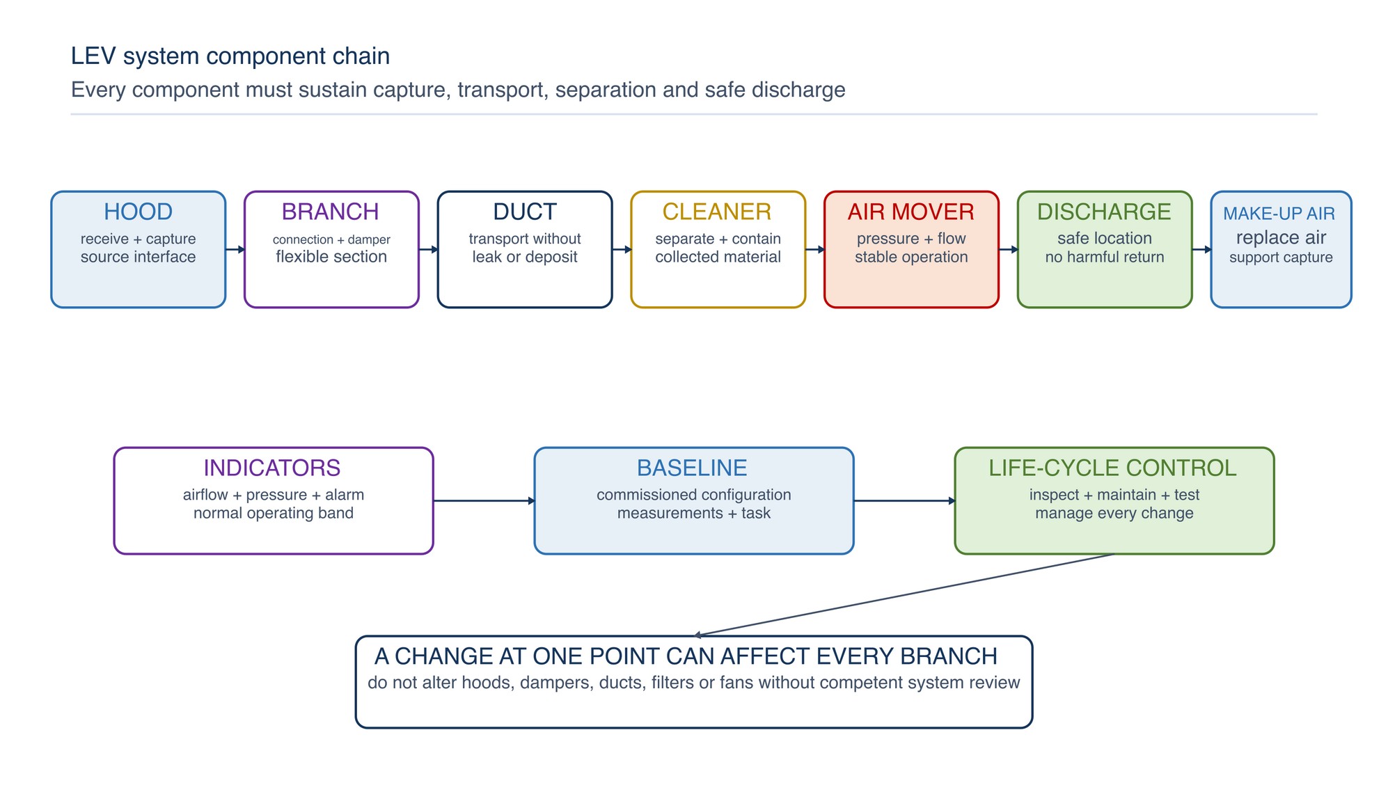
An LEV system is only as effective as its connected components:
| Component | Function | Typical loss-of-control condition |
|---|---|---|
| Hood or enclosure | Receives or captures contamination | Too far away, damaged, obstructed or poorly positioned |
| Branch connection | Carries air from one hood into the system | Loose joint, closed damper, crushed flexible section or material buildup |
| Ductwork | Transports contamination toward separation | Leakage, corrosion, dents, blockage, poor branch balance or deposition |
| Air cleaner or separator | Removes collected material from the airstream | Loaded, damaged, unsuitable, leaking or incorrectly serviced element |
| Air mover | Produces pressure and airflow | Wrong rotation, belt slip, wear, fouling, power loss or unstable operation |
| Discharge | Releases exhaust to a controlled location | Recirculation into air intakes, doors, neighbours or occupied areas |
| Make-up air | Replaces extracted air without harmful disturbance | Strong cross-draught, negative pressure, blocked inlet or contaminated supply |
| Indicators and controls | Show operating state or control condition | Alarm ignored, gauge unreadable, baseline absent or interlock defeated |
Changing one branch, hood, damper, filter or fan can affect other parts of a multi-branch system. Do not add extraction points or alter duct geometry without competent review and rebalancing.
Manage make-up air and cross-draughts
Extracted air must be replaced. If make-up air is insufficient, doors may become difficult to open, unwanted air may enter through dirty areas, combustion equipment may be affected and capture may deteriorate. If replacement air arrives as a high-velocity draught across an open hood, it can push contamination out of the capture zone.
Check the effect of:
- open roller shutters and doors;
- pedestal or ceiling fans;
- compressed-air jets;
- vehicle movement;
- air-conditioning diffusers;
- neighbouring exhaust systems;
- large moving workpieces; and
- the operator's body and clothing.
Arrange replacement air so it supports the intended flow pattern without cooling, discomfort or process interference. Smoke visualisation or another suitable tracer may help a competent person evaluate direction, but tracer substances must be appropriate to the workplace and must not create an exposure or product-contamination hazard.
Use wet methods as an engineered control
Wet methods can reduce airborne dust by applying liquid at the generation point and keeping collected material from drying. They work best when delivery remains continuous at the active contact and slurry is removed before it dries or spreads.
Before use, verify:
- the tool and electrical installation permit the method;
- the abrasive product is intended for wet use;
- the liquid does not react with the workpiece or contaminant;
- corrosion and finish-quality consequences are acceptable;
- splash and mist are controlled;
- floors and access routes remain safe;
- slurry cannot enter unsuitable drains; and
- the waste route suits the collected material.
NIOSH silica guidance supports wet methods and local extraction for silica-containing work, while also discouraging practices that re-suspend deposited dust. Apply that material-specific guidance only when silica may be present. [S311]
Commission against the actual process
Commissioning proves that the installed system performs its intended function with the real process, hood positions, branch configuration, make-up air and work practices. It should establish baseline information that later checks and examinations can compare.
Commissioning should address:
- process and contaminant description;
- hood type, position and intended operating envelope;
- operator and workpiece positions;
- airflow and pressure measurements at defined points;
- air-cleaner and air-mover performance;
- make-up air and cross-draught effects;
- discharge location and recirculation risk;
- exposure-control verification;
- alarms, indicators and interlocks;
- cleaning, waste and maintenance arrangements; and
- information, instruction and training for users.
DOSH guidance calls for a newly installed system to be tested and examined so design performance and adequate extraction can be verified, with the results retained as baseline data. [S302]
Perform a practical pre-use check
Operators should confirm that the control is available before generating contamination. A pre-use check does not replace competent inspection or testing.
| Check point | Acceptable operating indication | Stop and correct when |
|---|---|---|
| Correct extraction point | Intended hood or tool connection is fitted and positioned | Wrong branch, missing adapter or capture cannot follow the work |
| Physical condition | Hood, hose, duct and connections are complete and secure | Split hose, crushed section, loose joint, damaged hood or visible leakage |
| Airflow indication | Indicator, gauge or alarm shows the normal released condition | Reading is abnormal, absent, unstable or outside the defined operating band |
| Capture behaviour | Emission moves into the hood throughout the task envelope | Cloud escapes, crosses the breathing zone or spreads into the room |
| Collector condition | Differential indication and service state are acceptable | Filter or collector alarm, damage, overflow or unsafe dust accumulation |
| Make-up air | Doors, fans and room airflow support capture | Cross-draught defeats the hood or room pressure changes unexpectedly |
| Waste arrangement | Closed, compatible container and safe change method are ready | Waste route is open, incompatible, full or likely to release dust |
If extraction fails, stopping generation is normally the first safe response. Do not continue merely by opening a door, adding a fan or wearing an unselected respirator.
Keep the worker out of the contaminant path
Even a well-designed hood can be defeated by poor working position. The operator should not lean between the source and the capture point. Arrange fixtures, lighting and work height so the source remains visible without placing the face above a rising plume or in the tangential ejection path.
When a part must be rotated, plan the sequence so the capture point remains effective. For large work, divide the task into controlled zones and reposition movable extraction before restarting. Keep hoses supported so they do not pull a hand tool off line, snag the workpiece or encourage the operator to disconnect extraction.
Inspect, test and maintain systematically
DOSH guidance describes regular physical inspection, observation of use, airflow indication, air-cleaner condition and fan maintenance, together with competent testing and examination against baseline performance. [S302]
Maintenance should cover:
- hood damage, corrosion, coating loss and obstruction;
- hose wear, crushing, holes and insecure cuffs;
- duct leakage, deposits, dents, corrosion and loose access covers;
- damper position and branch balance;
- filter loading, seal integrity and cleaning mechanism;
- collector hopper or receptacle level;
- fan noise, vibration, rotation, drive and bearing condition;
- indicator, alarm and interlock operation;
- make-up air paths and discharge condition; and
- changes to process, material, tool, layout or work practice.
Isolate hazardous energy before opening, clearing or maintaining the system. Assess chemical, confined-space, fire, explosion, sharp-object, work-at-height and manual-handling hazards before internal access or collector servicing.
Control collected dust and filter changes
Capture transfers contamination from the air into hoses, ducts, filters, collectors and waste containers. It does not remove the need to control exposure during servicing.
Use a method that:
- stops and isolates the generating process and extraction equipment;
- prevents unexpected fan start or damper movement;
- avoids dropping, shaking or blowing dust from filters;
- contains contaminated elements during removal;
- uses compatible sealed waste containers;
- prevents mixing of reactive or incompatible materials;
- cleans external contamination before equipment leaves the controlled area;
- protects maintenance personnel for the assessed exposure; and
- returns the system to service only after inspection and functional checks.
Do not use ordinary domestic vacuum cleaners for hazardous industrial dust unless the complete unit and collection method are documented as suitable. Do not use compressed air or dry brushing where it can re-suspend hazardous dust.
Treat combustible or reactive dust separately
Some metal, organic, coating and polishing residues can burn, react or form an explosive atmosphere when finely divided. A collector that is appropriate for inert dust may be unsuitable for combustible metal dust, hot sparks or mixed residues.
Before connecting a process, determine:
- whether the dust can burn, react with water or react with another collected material;
- whether hot particles or sparks can reach the collector;
- whether ducts can accumulate hazardous deposits;
- whether the fan, filter, collector, bonding, grounding, discharge and protection systems suit the hazard;
- whether recirculation is permitted; and
- how collected material will be emptied, stored and disposed of.
Keep incompatible processes on separately assessed systems. Never connect a new metal, coating or polishing compound to an existing collector solely because a hose connection fits. Fire and explosion controls are developed further in Chapter 050.
Diagnose control loss from the source outward
| Symptom | Likely contributors | Corrective direction |
|---|---|---|
| Dust escapes at the contact point | Hood too far away, wrong side of ejection, workpiece obstruction or cross-draught | Stop; reposition or redesign capture and repeat the release check |
| Extraction weak at one branch | Closed damper, crushed hose, blockage, leak or branch imbalance | Isolate as required; inspect the branch and restore the verified configuration |
| All branches are weak | Loaded collector, fan or drive fault, blocked main, lost make-up air or system alteration | Stop affected processes and arrange competent system diagnosis |
| Filter loads unusually quickly | Excess generation, wrong separator, wet or sticky material, poor pre-separation or process change | Identify the changed contaminant and review collector suitability |
| Dust deposits inside duct | Transport is inadequate, duct is damaged or material is unsuitable for the system | Stop and assess fire, exposure and cleaning hazards before controlled removal |
| Hood capture changes when a door opens | Make-up air or cross-draught is uncontrolled | Stabilise room airflow and verify capture under normal operating conditions |
| Operator disconnects the hose | Poor ergonomics, excessive hose drag, blockage, noise or incompatible adapter | Correct the system and handling arrangement; do not normalise bypassing the control |
| Fume passes the breathing zone | Capture is behind the operator, too distant or not moved with the joint | Stop and place capture so the plume travels away from the breathing zone |
| Visible discharge near the building | Separator fault, leak, unsuitable discharge or recirculation | Stop affected work and prevent exposure until competent correction and verification |
Troubleshooting should compare the present condition with commissioning data and the normal operating indication. Random damper adjustment can shift the problem to another branch.
Know when to stop work
Stop airborne-contaminant generation when:
- the required extraction is unavailable or not connected;
- the airflow indicator or alarm is abnormal;
- visible emission escapes the defined capture zone;
- dust or fume crosses the breathing zone;
- a hose, duct, hood, filter, collector, fan or discharge is damaged;
- abnormal noise, vibration, heat or odour suggests system failure;
- a collector is full, leaking or receiving incompatible material;
- sparks or hot particles enter a system not assessed for them;
- a changed material, coating or process has not been assessed;
- cross-draughts or room pressure defeat capture;
- dust deposits indicate uncontrolled release or poor transport; or
- workers experience irritation, breathing difficulty, dizziness or other distress.
Move to a safe area, isolate as required, control access and report the condition. Restart only after the cause has been corrected and the complete control arrangement has passed its release checks.
Ventilation release checklist
Before the task begins, confirm:
- the workpiece, coating, abrasive, residue and adjacent processes are understood;
- airborne forms and exposure routes have been assessed;
- elimination, substitution, enclosure and wet methods have been considered;
- the correct extraction system is connected and released for the process;
- hood position follows the source and keeps contamination out of the breathing zone;
- guards, fixtures, hoses and extraction remain compatible with safe tool control;
- hoses, ducts, joints, dampers and access covers are intact;
- indicators, alarms and interlocks show the normal operating condition;
- make-up air and neighbouring activities do not defeat capture;
- filters, collectors and waste containers are in service condition;
- combustible, reactive and mixed-dust hazards are controlled;
- housekeeping will not re-suspend deposited dust;
- maintenance and filter-change work use isolation and containment;
- respiratory protection addresses the assessed residual exposure; and
- the operator knows the stop-work conditions and reporting route.
Noise and Vibration
The Noise and Vibration chapter begins on the following page of the printed handbook (page 429), outside this chapter extract.