
Production engineers, supervisors, operators, maintenance teams, safety personnel, QA/QC personnel, procurement staff and technical sales personnel
Bonded grinding wheels selected by diameter, thickness, centre type, bond grade, grain, grit, reinforcement, maximum permitted speed, application geometry, material suitability, contact load, expiry and storage. This chapter does not approve an MKTECH wheel, machine, operating speed, angle, pressure, material result or shelf-life rule.
Select and mount only an identified wheel whose product type, dimensions, centre, reinforcement, maximum permitted speed, material/application declaration, mounting parts, guard and current instructions match the machine and operation. Do not use a wheel that is damaged, altered, unidentifiable, expired where an expiry applies, improperly stored or outside its declared use. [S032; S063; S072; S073]
Chapter objectives
After this chapter, the reader should be able to:
- read a grinding wheel as a complete controlled specification;
- distinguish diameter, thickness, centre and reinforcement functions;
- explain grain, grit and bond grade without treating them as independent rankings;
- verify maximum permitted speed against the machine;
- screen material, application geometry and contact load;
- control expiry, storage, stock rotation and quarantine; and
- create a minimum wheel-selection record.
A wheel name is not a specification
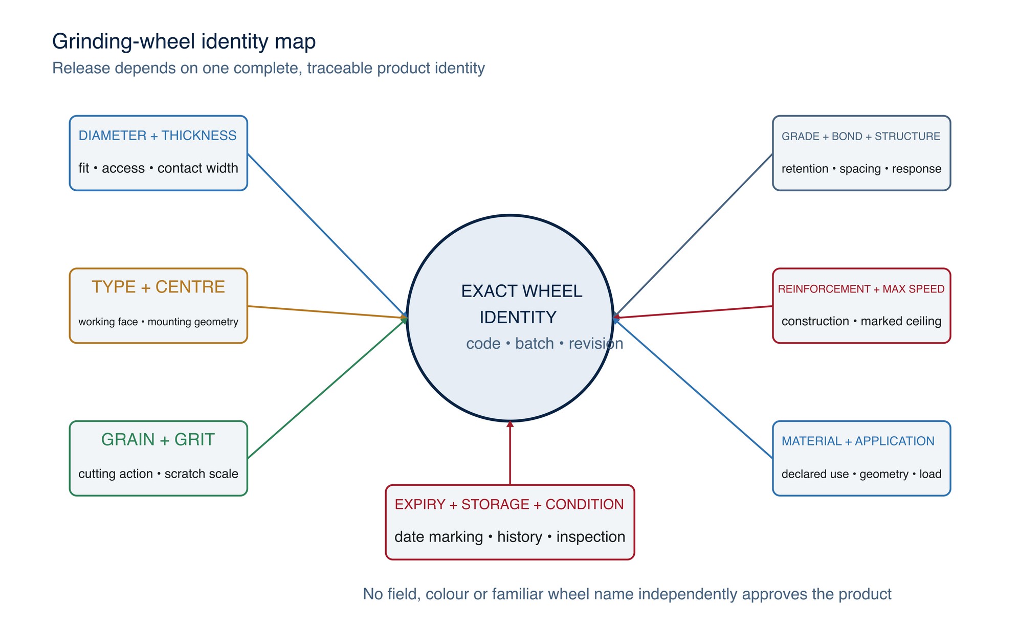
“Grinding wheel” describes a broad product form. Two wheels with the same diameter can differ in thickness, centre geometry, abrasive grain, grit, grade, bond, structure, reinforcement, mounting arrangement, speed rating and declared application. Colour is not a reliable cross-manufacturer code.
Start with the task: material, feature, stock allowance, access, required geometry, accepted surface and hazards. Then verify the wheel form, machine interface and declared use. Exact selection ends only after a representative controlled trial and approval.
Diameter, thickness and centre type
| Field | What it controls | Invalid shortcut |
|---|---|---|
| Outside diameter | Guard fit, machine capacity, peripheral speed and access | “A smaller wheel is always interchangeable” |
| Thickness | Contact width, stiffness, stock-removal behaviour, clearance and flange support | “Thicker always means stronger or faster” |
| Centre/bore type | Mounting geometry, flange/hub arrangement and wheel orientation | “If the bore fits, the wheel is approved” |
| Wheel shape/type | Working face, approach geometry and mounting system | “All bonded wheels can grind on the side” |
A depressed-centre wheel creates mounting clearance for right-angle grinding. A straight wheel, cup wheel or dish wheel carries a different load path and requires its declared machine, guard, flange and working face. Wheel types must not be improvised by adding washers, adapters or altered flanges.
Diameter also changes peripheral speed at a given RPM. The machine’s possible speed, wheel diameter and wheel maximum permitted speed must therefore be verified together. [S032; S063; S073]
Reinforcement and wheel construction
Reinforcement is an engineered part of some resin-bonded wheels. It supports the declared product design and intended loading, but it does not make every surface or operation permissible. The location, number and type of reinforcing layers are manufacturer-controlled design features.
Do not infer reinforcement from colour, thickness or appearance. Do not expose, trim, drill, reshape or repair a bonded wheel. A product marketed for combined cutting and grinding must be identified as such; a cutting wheel is not automatically approved for side grinding.
A Type 27 grinding-wheel specification should separately identify wheel construction, reinforcement, centre hole, declared applications, material coverage and maximum operating speed. Check every field on the exact wheel being selected. [S073]
Grain, grit and bond grade work together
The abrasive grain performs the cutting. Grit describes nominal grain-size classification. Bond holds the grains in the wheel. Grade describes the bond’s relative holding power; it is not the hardness of the abrasive grain itself.
| Selection field | General screening tendency | What prevents a universal rule |
|---|---|---|
| Grain family | Different fracture and chemical behaviours suit different materials and duties | Exact grain blend, bond and product design control actual response |
| Coarser grit | Larger chip space and stronger stock-removal tendency | May increase scratch depth, force and edge damage |
| Finer grit | Smaller scratch scale and finish-development tendency | Can load, rub or generate heat if the system is unsuitable |
| Softer grade | Releases dull grain more readily | May wear rapidly or lose form |
| Harder grade | Retains grain and form longer | May glaze or burn if dull grain is not released |
oSa explains that coarser grits generally support rough grinding while finer grits support higher surface quality. It also distinguishes grit size from wheel hardness and notes that harder work materials commonly call for a softer bond response.
Grain, grit, grade, structure and bond must be considered as related specification factors. These are screening principles only; exact wheels require product data and representative trials. [S071; S072; S075]
Material suitability is a declared property
Material suitability is not established by wheel colour, a generic grain name or successful use on another job. Obtain the exact manufacturer declaration for the substrate and application.
For stainless steel, confirm that the exact wheel is declared suitable and that contamination-control requirements are met.
For aluminium and other non-ferrous materials, loading, heat and reactive-dust hazards require a product specifically intended for the material and a suitable extraction/fire-control assessment. For masonry, concrete and stone, confirm the wheel and machine are intended for mineral materials and control silica exposure.
Mixed-material use can transfer contamination and invalidate surface acceptance. Segregate and identify wheels where the process requires it.
Maximum RPM is a ceiling, not a target
The wheel’s marked maximum permitted speed must be greater than or equal to the machine’s maximum possible speed for the fitted diameter and configuration. The operator does not “average” two ratings or rely on normal loaded speed. Variable-speed control does not justify mounting a wheel that is incompatible with the machine’s possible speed or declared operating range.
The abrasive maximum operating speed must be at least the machine's maximum spindle speed, and the specified guard must suit the wheel type and size. OSHA and FEPA separately address machine guarding, mounting and speed compatibility. [S032; S063; S073]
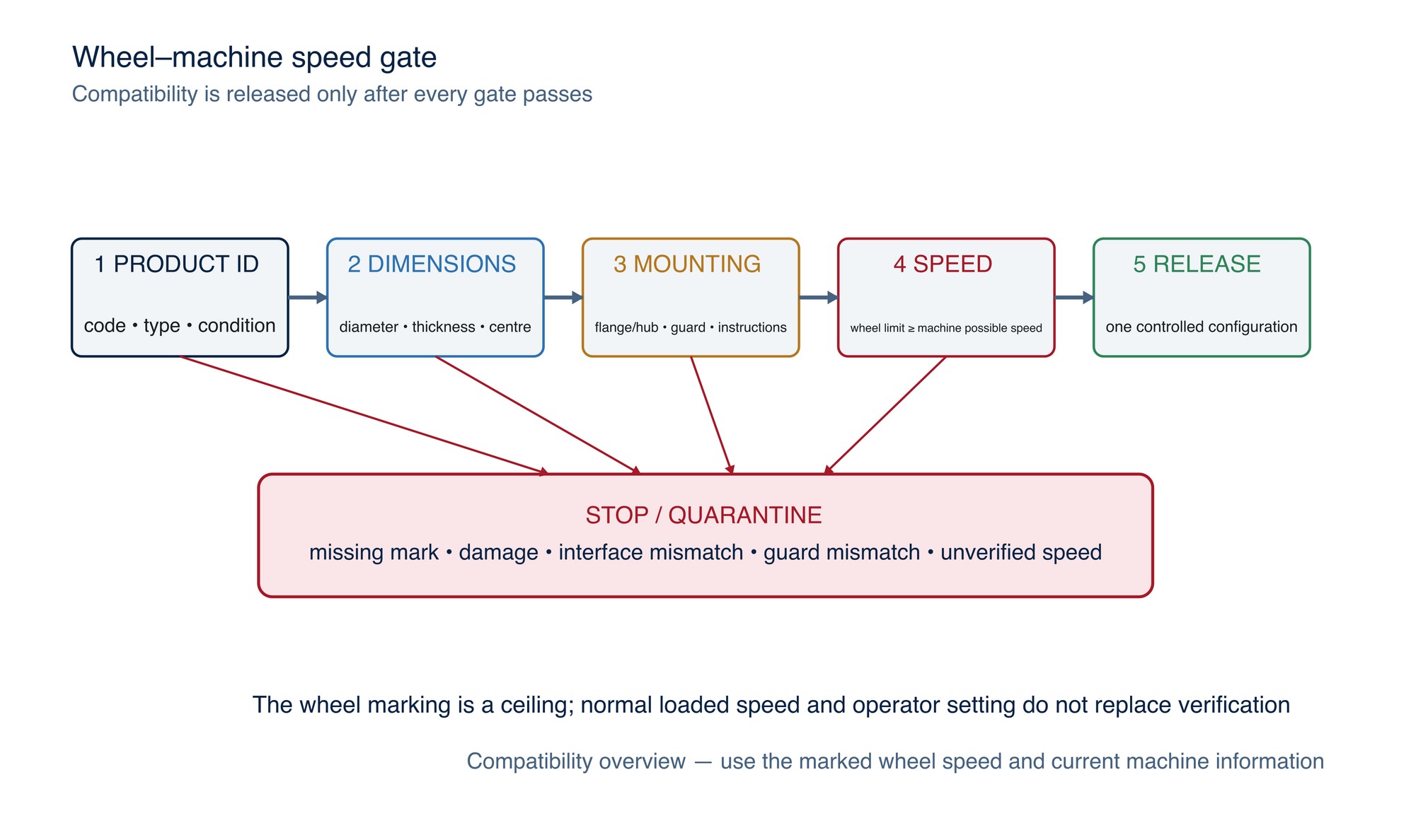
Stop when the wheel marking is missing, unreadable or contradictory; the machine speed cannot be verified; an adapter changes the approved interface; or the wheel/guard combination does not match current instructions.
Application angle and grinding pressure
Application angle determines which part of the wheel contacts the work and how load is distributed. Exact angles belong to the identified wheel type and manufacturer instructions; Chapter 013 will explain contact-area effects with original diagrams. This chapter does not prescribe one universal angle.
Pressure is likewise a process variable, not an operator-strength test. Too little effective load can encourage rubbing and glazing; excessive load can stall the machine, overheat the contact, damage the work, accelerate wheel wear or overload the wheel and operator. The acceptable range depends on wheel design, machine power/torque, contact area, material, geometry and cooling/extraction.
Product, machine, contact geometry and applied load must be validated as one operating system. Never transfer pressure or performance expectations from a different wheel construction or test condition. [S073]
Expiry, shelf life and storage
“Bonded wheel” does not imply one universal expiry rule. Resin-bonded hand-held wheels may carry a use-by date under the manufacturer’s applied safety standard. Other wheel families can have different manufacturer recommendations. Never replace a marked date with a generic handbook interval.
oSa states that expiry marking applies to specified resin-bonded tools for hand-held machines under EN 12413 and explains dry, frost-free, stable storage in original packaging on a flat surface. Moisture can reduce resin-bonded wheel strength. The exact marked date and current manufacturer instruction control the product. [S072; S074]
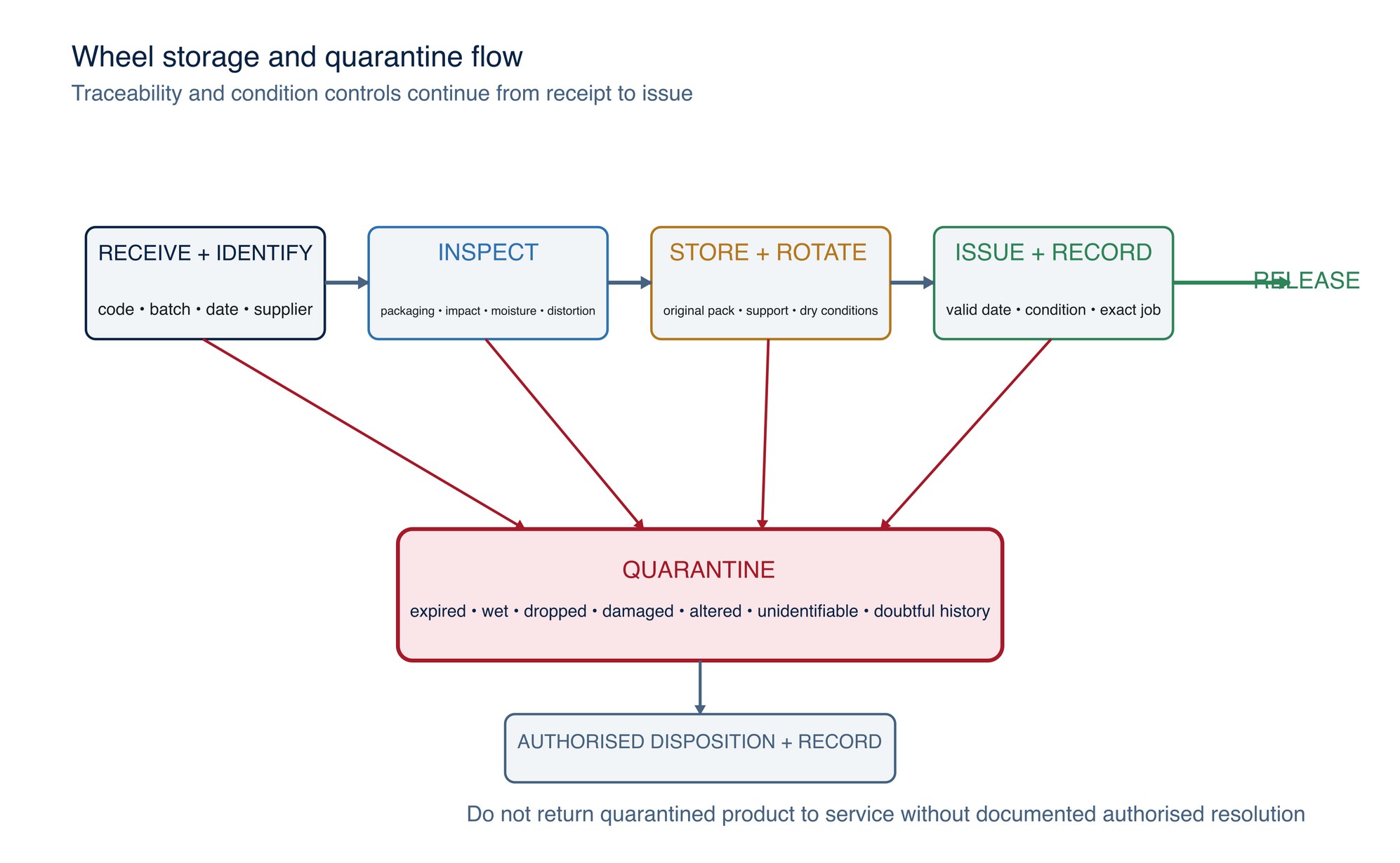
Control stock by:
- recording manufacturer, product code, batch/lot and date markings at receipt;
- inspecting packaging and wheels for impact, moisture, distortion and contamination;
- storing by wheel type in the original packaging with suitable support;
- maintaining dry, stable environmental conditions required by the manufacturer;
- issuing by earliest valid use-by date or approved first-in/first-out rule;
- quarantining expired, damaged, wet, dropped, altered or unidentifiable wheels; and
- documenting disposition through an authorised process.
Controlled selection workflow
- Define material, feature, stock allowance, access and accepted output.
- Identify the machine, guard, flange/hub and maximum possible speed.
- Select the declared wheel type and working face for the operation.
- Match diameter, thickness, centre and mounting arrangement.
- Match grain, grit, grade, bond, structure and reinforcement to the declared duty.
- Verify material suitability, contamination controls and environment.
- Verify marked maximum permitted speed and any expiry/use-by requirement.
- Inspect wheel, packaging, storage history and mounting parts.
- Apply the manufacturer’s angle, load, mounting and start-up instructions.
- Run a representative controlled trial and record removal, heat, geometry, finish, wear and safety observations.
- Release one exact wheel–machine–material–operation revision.
Troubleshooting by wheel signal
| Signal | Possible selection causes | Controlled response |
|---|---|---|
| Wheel glazes or stops cutting | Grade too hard for the system, insufficient effective load, wrong grain/grit, low machine response | Stop; verify complete specification and process; do not add uncontrolled force |
| Wheel wears unusually fast | Grade too soft, excessive load, wrong angle/contact, unsuitable material or damaged wheel | Hold output; inspect wheel, machine and application |
| Burning or discolouration | Rubbing, loading, excessive contact, unsuitable grit/grade, weak cooling/extraction | Stop; protect the part; correct and revalidate |
| Edge digging or poor geometry | Wrong wheel shape/thickness, angle, contact width, pressure or operator control | Stop; reassess wheel form and approach |
| Vibration, noise or runout | Damage, contamination, mounting error, flange mismatch, imbalance or machine defect | Isolate; quarantine wheel and inspect system |
Wheel selection in practice
Read the complete wheel marking before selection. Match shape and centre type, diameter, thickness, bore, grain, grit, grade, bond, structure and reinforcement to the declared material and operation. Confirm the guard, flanges and machine speed are suitable for that exact wheel; maximum marked speed is a ceiling, not a recommended setting.
Store wheels dry and protected from impact, temperature extremes and uncontrolled stock rotation. Inspect the wheel and its marking before mounting, and remove damaged, expired or unidentified items from service. Refer to the product label, Technical Data Sheet, or MKTECH representative.
Wheel selection and setup record
For repeatable selection, record the task, material, geometry, allowance, required finish, machine or asset, machine maximum speed, guard, flange or hub, wheel manufacturer, code, batch or lot, shape/type, diameter, thickness, centre/bore, grain, grit, grade, bond, structure, reinforcement, marked maximum speed, declared material/application, expiry or use-by marking, storage condition, working method and inspection result.
Grinding Angles and Contact Area
Chapter 013 — Grinding Angles and Contact Area begins on the following page of the printed handbook (page 96), outside this chapter extract.