
Production engineers, supervisors, grinding operators, welders, fettlers, inspectors, QA/QC personnel, safety personnel, maintenance teams, trainers and technical sales personnel
Controlled heavy removal of excess metal, casting gates and riser remnants, weld reinforcement, temporary attachments, flash, scale and machining allowance using identified abrasive systems. This chapter does not prescribe an MKTECH product, speed, pressure, angle, pass length, overlap, removal rate, wheel-change point, temperature limit, finish value or dimensional acceptance criterion.
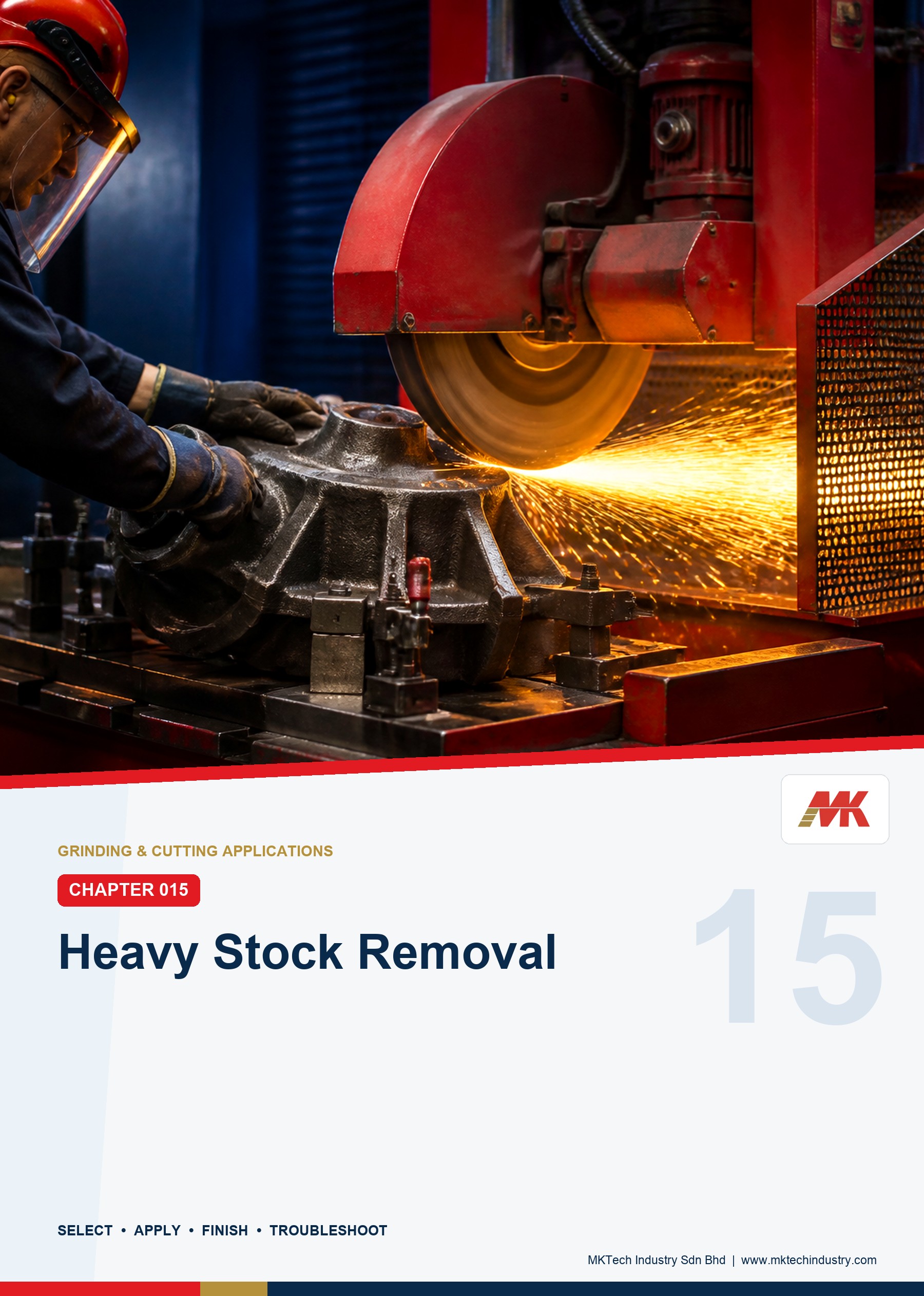
Heavy stock removal combines high power, high reaction force, rapidly changing geometry, sparks, hot particles, dust, noise, vibration and abrasive wear. Work only from an authorised removal boundary and inspection plan. Use an identified abrasive on a compatible guarded machine, secure the work, control ejected material and exposure, and stop for wheel damage, loss of control, abnormal vibration, loading, glazing, overheating, distortion, parent-surface contact, uncertain remaining section or any condition outside the approved method. [S007; S008; S009; S014; S017; S018; S032; S063; S080; S081]
Chapter objectives
After this chapter, the reader should be able to:
- define the removal boundary before selecting a product;
- select a product family by material, geometry, machine and required transition;
- distinguish insufficient cutting action from useful cutting and overload;
- plan pass length, travel and inspection intervals to manage heat and geometry;
- recognise wheel wear, loading, glazing, imbalance and damage signals;
- protect edges, adjacent faces, thin sections and finished references;
- transition from bulk removal to blending before the final contour is endangered;
- control distortion and workholding throughout the operation; and
- create a traceable heavy-stock-removal and inspection record.
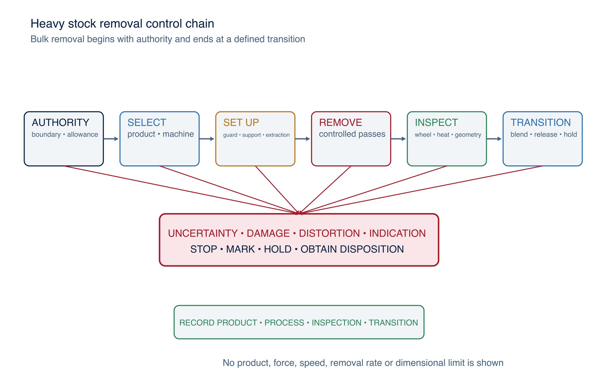
Define the material that may be removed
Heavy stock removal is not a licence to grind until the surface “looks right.” Identify the starting condition, the material that is authorised for removal and the geometry that must remain. Typical purposes include reducing a casting gate or riser remnant, removing flash, dressing an approved weld profile, removing a temporary attachment, correcting a documented machining allowance or preparing an authorised repair.
The release package should identify:
- component and material;
- removal purpose and responsible authority;
- protected surfaces, edges, section and datum features;
- final contour or remaining allowance;
- inspection stages and stop conditions;
- permitted process families; and
- disposition for cracks, cavities, inclusions or other unexpected indications.
HSE heavy-fabrication guidance advises minimising manual rework through accurate preparation and alternative processes where reasonably practicable. Its foundry guidance similarly treats casting and runner design, automatic fettling, cut-off, cropping and jigs as possible ways to reduce unnecessary manual grinding. These are risk-control principles, not a universal process substitution. [S080; S081]
Select the complete removal system
Select the abrasive product, machine, support element and workholding as one system. Grain, grit, grade, structure, bond, reinforcement, wheel form, diameter and thickness influence response; machine power, speed, guard, spindle, handle position and access determine whether that response can be controlled. A product described as aggressive is not automatically suitable for the material, edge, cavity or remaining allowance. [S025; S029; S032; S055; S063; S071–S075]
| Application condition | Selection question | Primary control risk |
|---|---|---|
| Broad, accessible excess on robust section | Can the declared working face remove material while preserving the stop reference? | Excessive footprint, heat spread or uncontrolled breakthrough |
| Narrow gate, riser, lug or weld crown | Can the product reach the high material without contacting the parent surface or adjacent face? | Side contact, edge gouging or concentrated heat |
| Internal corner or restricted feature | Can the guard, hub, machine head and product enter and leave safely? | Trapping, kickback, hidden contact or poor inspection access |
| Thin, unsupported or distortion-sensitive part | Is heavy grinding the correct process, and can the part be supported and monitored? | Warping, vibration, local thinning or loss of datum |
| Coated, stainless, aluminium or mixed-material work | Is the abrasive and collection route compatible and segregated? | Contamination, loading, hazardous dust or coating damage |
Manufacturer examples can help define fields for a trial, but their product rankings, grit choices, service life and productivity claims do not transfer to an MKTECH product. Compare candidate systems under one controlled test method using material removed, elapsed contact time, abrasive use, geometry, heat, finish, exposure and operator-control observations. [S036; S073]
Pressure is a controlled response variable
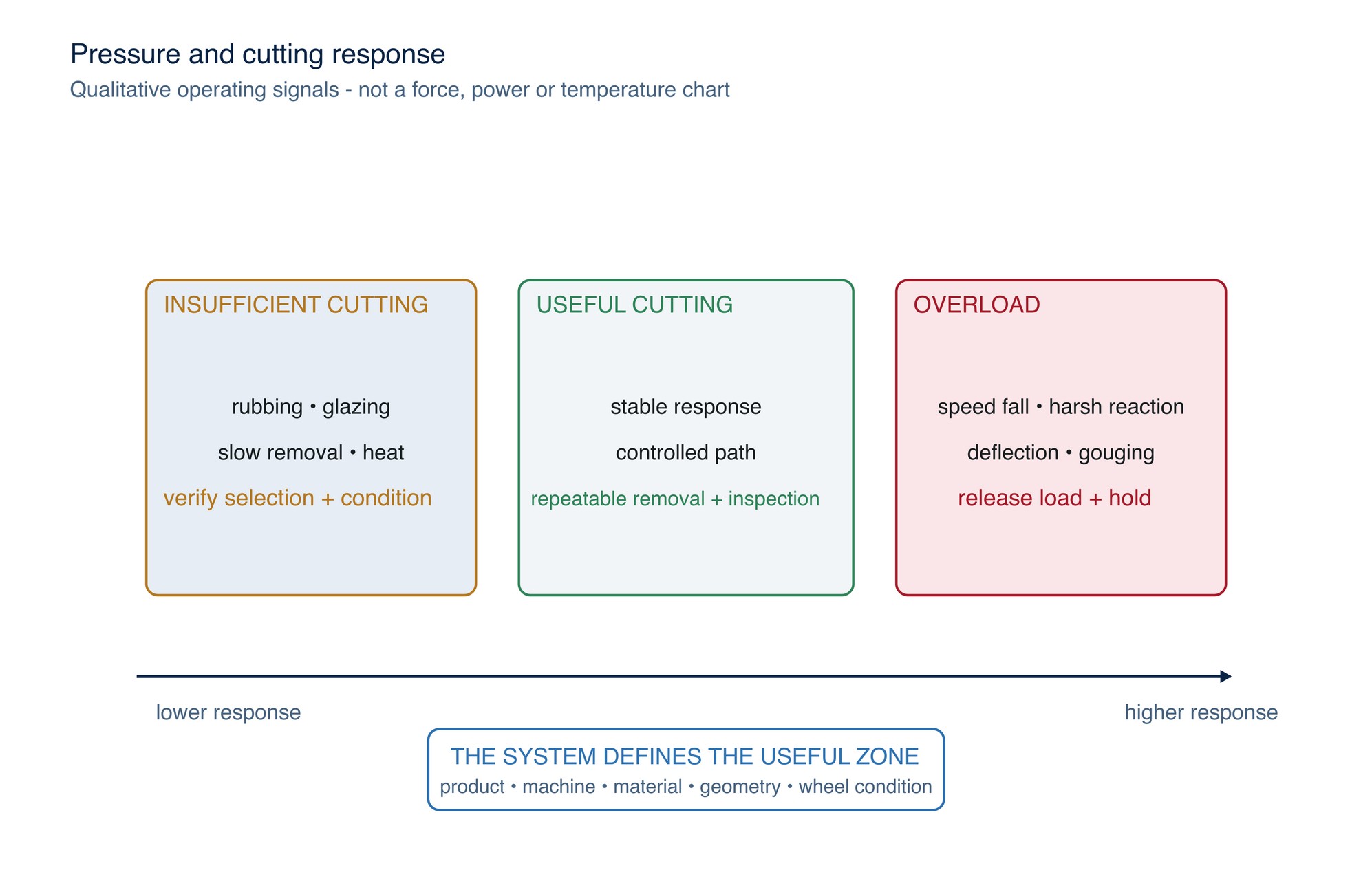
Pressure should produce stable cutting action without forcing the product, stalling the machine, deforming the wheel, enlarging the contact area or making the operator fight the reaction. Grinding energy is divided among rubbing, ploughing and chip formation; a bright spark stream or loud sound alone does not prove efficient removal. [S025; S030; S031]
Insufficient cutting action may present as rubbing, polishing, glazing, smearing, slow removal or rising heat with little useful output. Before adding force, check product suitability, wheel condition, working face, machine power and speed under load, access and material compatibility.
Useful cutting action is stable and repeatable. The machine remains controllable, the product cuts on its declared face, chips and sparks discharge safely, the reference remains visible, and removal occurs without abnormal heat, vibration or surface damage.
Overload may present as falling speed, severe reaction, wheel deflection, harsh vibration, rapid edge breakdown, local gouging, excessive heat or loss of path control. Release pressure and stop. Do not convert inadequate selection or a worn product into a force problem.
HSE foundry guidance warns that a wheel that has lost cutting action can encourage operators to press harder, increasing distortion, vibration and the risk of wheel breakage. It recommends selection for cutting efficiency rather than maximum wheel life. [S080]
Design passes to control heat and geometry
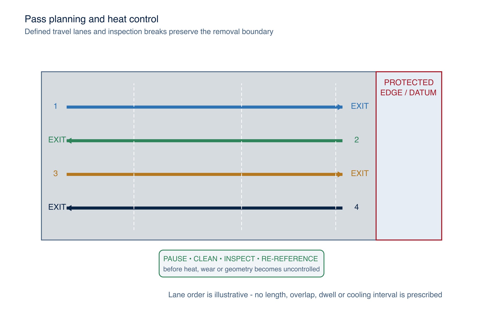
A heavy pass should have a defined start, direction, length, exit and inspection interval. Do not dwell at starts, stops, high spots, edges or corners. Use a repeatable travel pattern that prevents one location from receiving continuous contact while nearby areas remain untouched.
Pass length is not a universal distance. It depends on available high material, part stiffness, heat path, access, wheel width, contact footprint, machine control and the visibility of the stop reference. A long pass can spread energy but may cross protected geometry; a short pass can improve access but may concentrate heat and create scallops. Record the representative method rather than relying on “keep moving.”
Heat management begins with cutting efficiency. When more input becomes rubbing or ploughing instead of chip formation, local heat can rise without useful removal. Control heat by correcting the complete system: selection, condition, contact, travel, dwell, sequence, workholding and approved cooling or pause method. Never introduce water, compressed air or another coolant unless the product, machine, material, electrical controls and workplace procedure allow it. [S025; S030; S031]
Protect edges, references and adjacent surfaces
Edges concentrate contact and reduce the margin for correction. Establish a protected offset from finished edges, holes, radii, sealing faces, machined datums and thin walls. Approach the final boundary with the approved lower-intensity process rather than carrying a bulk-removal product across it.
On external edges, avoid rolling the product over the corner and rounding a feature that must remain sharp. On internal corners, avoid trapping the product or using an undeclared side face. On raised bosses, ribs and welds, confirm which surface is the datum and protect the surrounding parent material.
Where a part can flex, provide support close enough to control movement without concealing the work or creating a pinch point. If the support, clamp or fixture moves, stop and re-establish the references. Heavy removal on a loose or resonant part is not corrected by gripping the machine harder.
Wheel condition changes the process
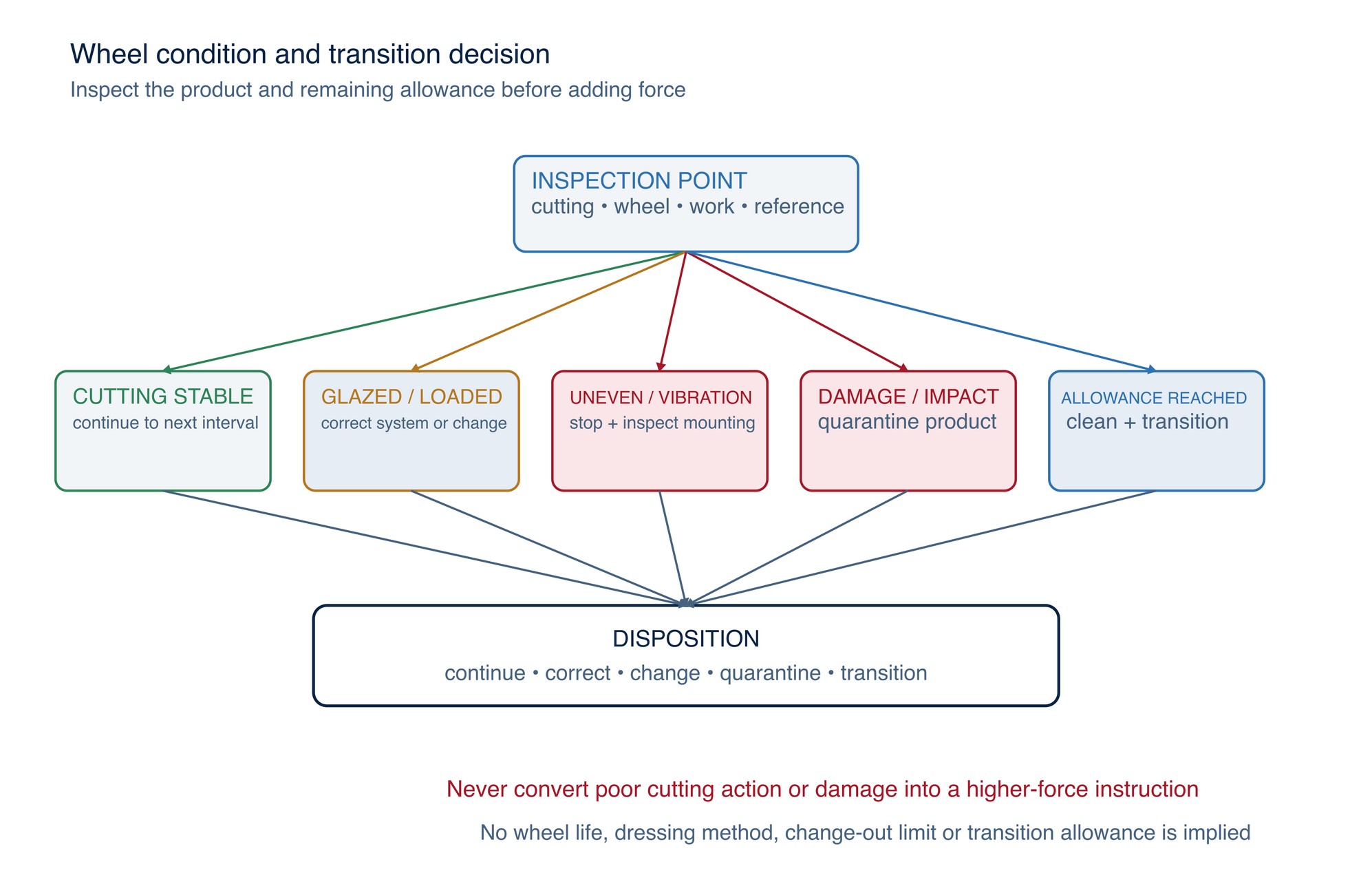
Wheel wear changes diameter, contact footprint, exposure, balance, edge condition and the relationship between guard, work and handles. The operator must inspect the product before use and at defined intervals, not only when removal becomes slow. FEPA and OSHA sources require product inspection, correct use, compatible speed, guarding and removal of damaged wheels from service. [S007; S018; S032; S063]
Normal controlled wear is expected only within the product instructions and trial record. Glazing is a dull working surface with reduced cutting action. Loading is retained work material or debris that obstructs cutting. Uneven wear changes contact and may cause vibration or path drift. Damage includes cracks, chips, impact marks, exposed reinforcement outside the declared condition, hub damage or any suspect change.
Do not dress, clean, trim or reshape a hand-held bonded or coated product unless that action is expressly permitted by its manufacturer and the workplace method. Never strike, drop or improvise a wheel-restoration action. When cutting action deteriorates, inspect the complete system and change the product at the approved condition—not after higher force has hidden the problem.
Transition to blending before the final contour
The bulk-removal stage should stop with a defined allowance for the next process. Waiting until the wheel reaches the final surface leaves no controlled margin for correcting scallops, heat tint, wheel marks or local lows.
Transition when any of the following occurs:
- the remaining high material equals the approved blending allowance;
- the bulk product can no longer contact only authorised material;
- the reference surface or edge is approaching the contact footprint;
- the required contour, finish or inspection sensitivity exceeds the bulk process capability;
- heat, vibration or wheel condition becomes unstable; or
- a hold-point inspection is due.
Clean the area, inspect from more than one direction and record the remaining condition before changing products. The blending stage requires its own product identity, compatibility, working-face declaration and acceptance criteria. Do not use a finer product merely to conceal heavy-grinding damage.
Control distortion and residual geometry
Distortion risk depends on part thickness, stiffness, restraint, residual stress, material, heat input, removal pattern and the amount and location of metal removed. The safest control may be reducing the need for manual grinding through better preparation, cutting, machining or fixture design. HSE specifically identifies precision preparation and alternative processes as ways to reduce grinder rework in heavy fabrication. [S081]
Where grinding remains authorised:
- support and clamp the part to the approved fixture plan;
- retain access to datum and inspection surfaces;
- distribute removal according to the approved sequence;
- avoid continuous work at one edge, corner or thin section;
- stop for movement, bowing, twist, clamp release or reference drift; and
- inspect geometry after unclamping when the plan requires a free-state result.
Do not straighten a distorted component by additional grinding. Hold it for engineering disposition.
Controlled heavy-removal workflow
- Identify the component, material, starting condition and traceability.
- Confirm the exact removal purpose, boundary, remaining allowance and protected geometry.
- Verify the drawing, procedure, risk controls and inspection plan.
- Decide whether grinding is the correct process or whether cutting, machining, cropping or automation is more suitable.
- Select and record the machine, guard, handle arrangement, abrasive specification, support element and working face.
- Verify speed compatibility, condition, mounting, workholding, access, lighting, extraction and ejected-particle controls.
- Mark references where permitted and record the starting profile.
- Establish the approved pressure-response, travel, pass and inspection method on representative work.
- Remove material in controlled passes without crossing protected boundaries.
- Inspect wheel condition, part heat, geometry, workholding and remaining allowance at defined intervals.
- Stop and quarantine for damage, abnormal vibration, unexpected indications, distortion or loss of reference.
- Clean, inspect and record the condition at the transition to blending or final release.
Troubleshooting heavy-removal signals
| Signal | Possible system cause | Controlled response |
|---|---|---|
| Slow removal with rising heat | Glazing, loading, unsuitable specification, low power under load or rubbing contact | Stop; verify wheel condition, specification, machine delivery and working face before changing force |
| Machine speed falls or reaction becomes severe | Excessive load, large contact footprint, wrong product, unstable access or weak machine | Release load; hold and reassess the complete system |
| Deep scallops or local lows | Dwell, short repeated strokes, pivoting, narrow contact or chasing a high spot | Stop; inspect remaining allowance and restore a controlled pass pattern |
| Edge rounds or adjacent face is marked | Contact crossed the boundary, product width is unsuitable or support moved | Stop immediately; measure the protected feature and obtain disposition |
| Wheel wears unevenly or vibration increases | Side loading, incorrect working face, damage, mounting issue or changing access | Stop; isolate the product and inspect machine, mounting, guard and work |
| Part bows, twists or moves in the fixture | Local heating, uneven removal, inadequate support, restraint change or released residual stress | Stop; allow the approved stabilisation condition and obtain geometric/engineering review |
| Surface smears or wheel loads | Material incompatibility, poor chip clearance, contaminated product or excessive dwell | Stop; segregate affected work and verify the approved material-specific system |
| Final contour is close but bulk marks remain | Transition occurred too late or no allowance was reserved | Hold; do not chase the marks below the boundary —obtain disposition |
Applying heavy-removal guidance
Mark the removal boundary and the geometry that must remain before work begins. Choose a product declared for the material, machine and heavy-removal action, then use controlled passes that keep the abrasive cutting without excessive dwell. Inspect the wheel, heat pattern, edges, thin sections and reference surfaces at planned intervals.
Transition to a less aggressive stage while sufficient allowance remains to remove the heavy-grinding scratch pattern. Do not pursue removal rate at the expense of parent-material thickness, weld profile, distortion, cracking, vibration or operator exposure. Refer to the product label, Technical Data Sheet, or MKTECH representative.
Heavy-removal process record
For repeatability, record the component and material; drawing and procedure revision; removal purpose; starting profile; authorised boundary; protected geometry; target and remaining allowance; machine, guard and handles; exact abrasive and batch; speed compatibility; support element and working face; workholding; access and extraction; load-control method; pass direction, length and inspection interval; wheel condition; heat and distortion observations; material removed where measured; transition condition; product change; unexpected indications; disposition; and dimensional and finish results.
Grinding Thin Sheet
The “Grinding Thin Sheet” chapter begins on the following page of the printed handbook (page 119), outside this chapter extract.