
Production engineers, supervisors, grinding operators, welders, sheet-metal workers, inspectors, QA/QC personnel, safety personnel, maintenance teams, trainers and technical sales personnel
Controlled grinding and blending of authorised weld and surface high spots on thin, distortion-sensitive sheet. This chapter does not define “thin” by a universal thickness and does not prescribe an MKTECH product, speed, pressure, angle, pass length, lane order, cooling interval, weld sequence, support spacing, temperature, finish value, remaining section or profile tolerance.
Thin sheet can move, vibrate, buckle, dish, bow, twist or lose section before the change is obvious. Grinding adds local heat and force to geometry that may already contain welding stress and restraint. Work only from the current drawing, welding and grinding procedures, support plan and inspection plan. Use an identified abrasive on a compatible guarded machine; secure the work without hiding movement or creating a hard fulcrum; and stop for heat concentration, reference drift, flexing, vibration, discolouration, surface damage, unexpected indications, loss of support or any uncertainty about remaining section or free-state profile. [S007; S008; S009; S014; S017; S018; S032; S063; S082–S084]
Chapter objectives
After this chapter, the reader should be able to:
- explain why thin sheet is sensitive to local heat, force, restraint and metal removal;
- define the approved profile and protected section before grinding;
- distinguish fixture support from an abrasive backing or support product;
- control pressure, footprint, pass direction, dwell and inspection intervals;
- select a controllable product family without transferring generic settings;
- coordinate grinding with the approved welding and distortion-control sequence;
- inspect the part both supported and free-state when the plan requires it;
- respond correctly to flexing, heat concentration, bowing and reference drift; and
- create a traceable thin-sheet grinding and profile-inspection record.
Establish the profile authority
“Thin sheet” is an application condition, not a universal thickness category. Sensitivity depends on alloy, thickness, span, formed shape, stiffeners, openings, weld position, residual stress, restraint and the amount and location of material removed. The drawing, engineering plan or qualified procedure must define the applicable part and acceptance criteria.
Before selecting an abrasive, identify:
- component, material, nominal thickness and traceability;
- weld, seam, attachment or surface condition to be treated;
- material that may be removed and material that must remain;
- finished face, edge, datum, feature and cosmetic zones;
- required weld profile, remaining section and surface condition;
- fixture and support condition during processing and inspection;
- required free-state inspection after release from restraint; and
- hold points for distortion, unexpected indications or uncertain profile.
Grinding cannot convert an unapproved weld, distorted assembly or dimensional nonconformance into an acceptable condition by appearance alone. If the controlling requirement is missing or contradictory, mark the area, protect the evidence and obtain disposition.
Why thin sheet distorts
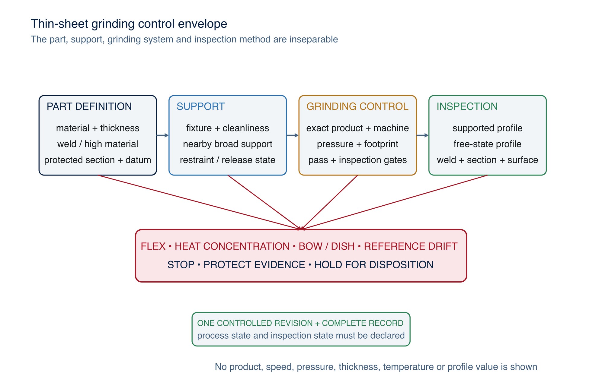
Thin sheet has limited bending stiffness compared with a thicker or more deeply formed part. A local grinding footprint can deflect the surface under force, while friction and chip formation create a concentrated heat source. Removing weld or parent material can also release locked-in stress or change the local stiffness.
TWI describes welding distortion as the result of non-uniform expansion and contraction under restraint, with permanent deformation possible when local stresses exceed the material response. It identifies longitudinal and transverse shrinkage, angular distortion, bowing or dishing, buckling and twisting as distinct outcomes. Thin plate may buckle elastically and appear rippled or dished. [S082]
A 2024 peer-reviewed study of thin-walled bearing grinding similarly found machining heat and stress to be principal deformation mechanisms, with greater heat entering the workpiece associated with higher thermal stress and deformation. Its geometry and precision process differ from hand-held sheet grinding, so only the mechanism is retained here; its parameters are not transferable. [S084]
The practical consequence is that grinding variables cannot be managed separately. Pressure changes deflection and contact; contact changes heat; heat changes stress and profile; support changes apparent profile; and removing restraint can reveal movement that was hidden while clamped.
Support the work without falsifying it
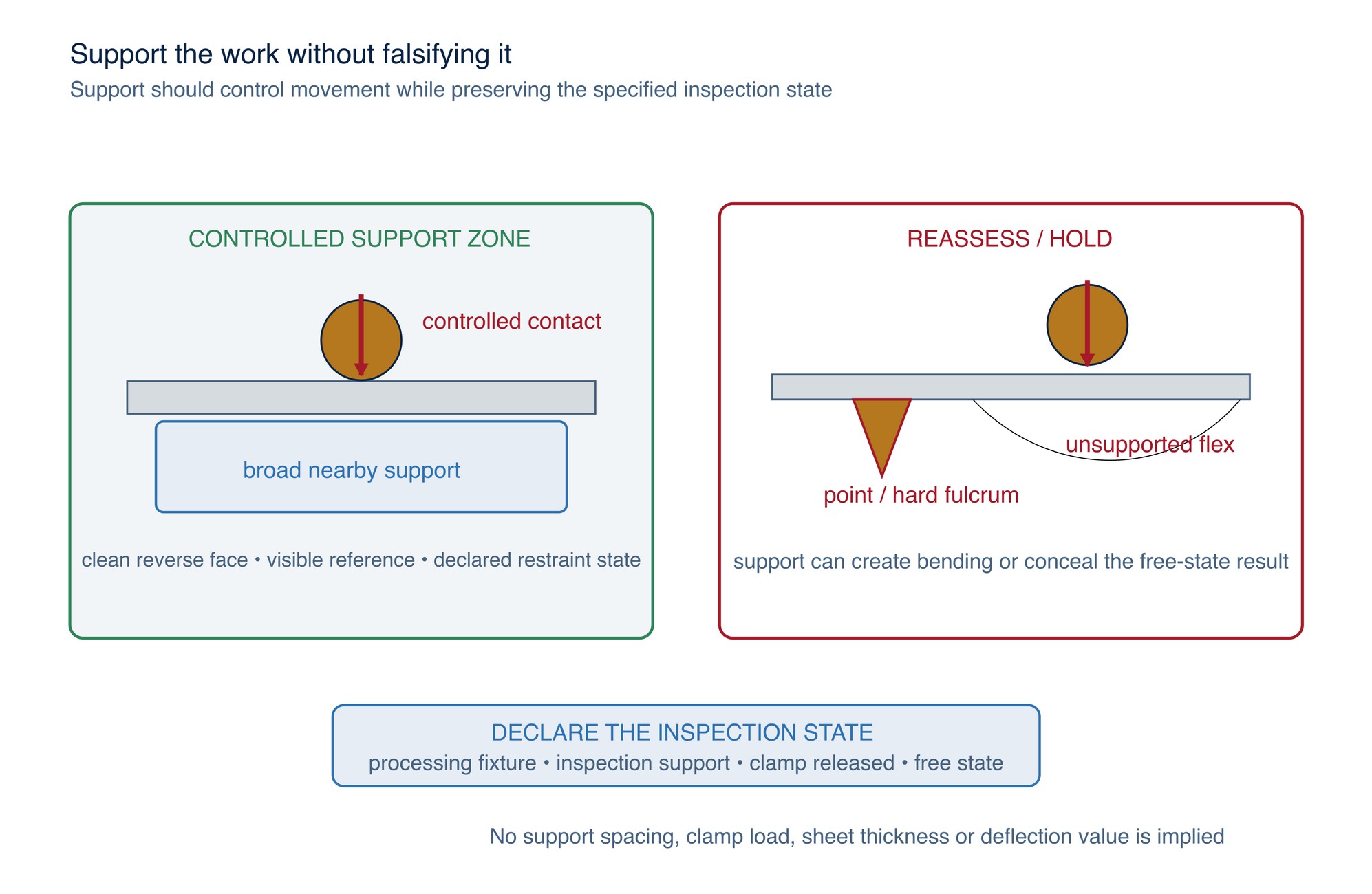
The work-support or fixture plan must control vibration and excessive flex while preserving access, visibility, cleanliness and the intended datum condition. This support is different from an abrasive backing pad, contact wheel or support element, which is part of the abrasive–machine system.
Use broad, stable support close to the working zone where the approved fixture plan permits it. Avoid point supports, unprotected hard edges or clamp positions that turn grinding force into a local bend. Do not place support over hot debris, abrasive grain, swarf or contamination that can imprint or scratch the reverse face.
Support can hide distortion. Record whether the profile is inspected:
- in the processing fixture;
- on the specified inspection support;
- after clamps are released; or
- in a defined free state after the approved stabilisation condition.
If the part changes shape as a clamp is released, do not force it flat for measurement or grind the new high point automatically. Preserve the condition and obtain engineering or quality disposition.
Control pressure through system response
The objective is stable cutting without visible sheet deflection, machine overload, abrasive smearing or loss of path control.
Pressure is not a transferable number. It is a controlled response of the exact abrasive, support element, machine, working face, material, sheet geometry, fixture and operator method.
Before increasing pressure, check whether the abrasive is suitable, sharp, clean and used on its declared face; whether the machine maintains the required operating condition; and whether the footprint is too wide, rigid or concentrated for the available high material.
Insufficient cutting may show as rubbing, glazing, loading, smearing, discolouration or rising heat with little removal.
Stable cutting gives a predictable path, controllable reaction and visible reference without sustained deflection. Overload or poor support may show as oil-canning, flutter, harsh vibration, falling speed, edge digging, rapid heat, gouging or the sheet moving with the tool.
If the surface flexes under contact, stop. Adding force can remove material from the temporarily deflected shape and leave a low area when the sheet springs back.
Plan direction, sequence and dwell
A controlled pass has an identified start, travel direction, exit and inspection point. Do not dwell at the start, end, weld stop, edge, corner, hole or isolated high spot. Do not repeatedly chase the brightest spark or highest-looking point without cleaning and re-referencing the surface.
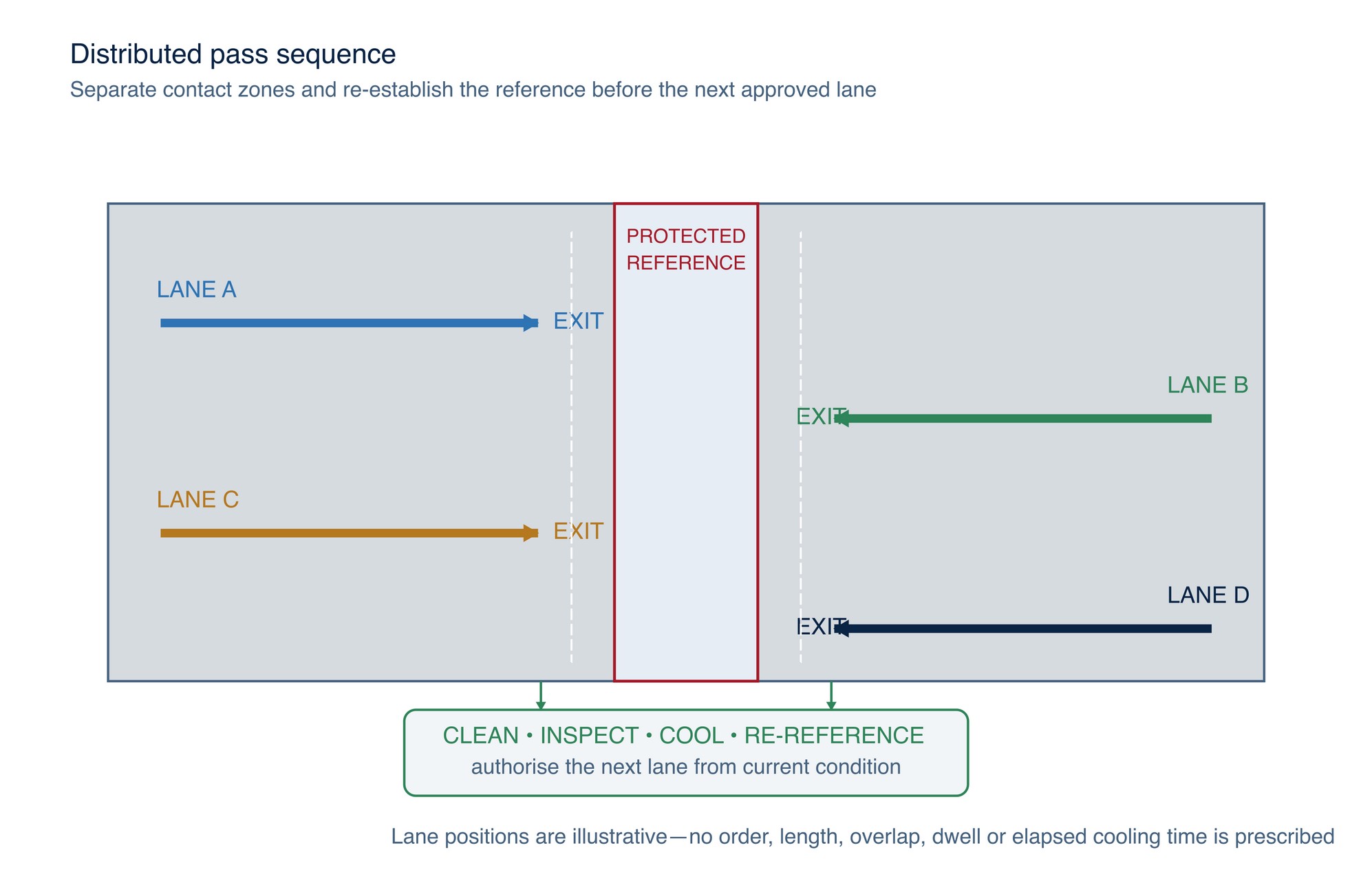
The pass sequence should distribute contact so that one zone does not receive repeated heat and force while the surrounding sheet remains untouched. Alternating or separated lanes can be assessed during a representative trial, but there is no universal left-to-right, cross-hatch or skip pattern. The approved sequence depends on the high material, weld layout, sheet stiffness, support, access, abrasive footprint and inspection method.
TWI advises that weld run order and technique can be crucial to distortion control and describes balanced, back-step and skip approaches for welding. These are welding-fabrication principles, not automatic grinding instructions. Grinding must follow the specified weld and distortion-control sequence. [S083]
Use cooling intervals as inspection gates
A cooling interval is not merely elapsed time. It is a controlled pause in which contact stops, the surface is cleaned by an approved method, heat distribution and part condition are observed, the reference is restored, and the next action is authorised.
Set interval criteria during representative validation using the actual material, thickness, weld, support, abrasive, machine, access and environment. Useful observations can include:
- growing local heat relative to nearby material;
- heat tint or coating change where relevant;
- abrasive loading, glazing or reduced cutting;
- sheet flutter, oil-canning, bow, dish or reference movement;
- fixture or clamp movement;
- loss of the high-material boundary; and
- a scheduled dimensional, profile or visual hold point.
Do not prescribe a fixed number of seconds from generic guidance. Do not apply water, compressed air, solvent or another cooling or cleaning medium unless the abrasive, machine, electrical controls, material, coating, contamination plan and workplace procedure expressly permit it. Rapid or uneven cooling may itself affect condition and inspection evidence.
Select for control, not maximum removal
Heavy stock-removal products may have a footprint, stiffness or removal response that is unsuitable for a distortion-sensitive sheet. Select the least aggressive system that can meet the authorised removal and quality requirement with adequate control. Product-family names do not establish suitability.
| Candidate system characteristic | Thin-sheet screening question | Control concern |
|---|---|---|
| Rigid bonded wheel or rigid contact | Can it remain only on authorised high material without side contact or local bending? | Gouging, concentrated heat, edge attack or undeclared working-face use |
| Coated disc with separate support element | Are disc, support element, fastener, speed and flexibility compatible as a declared system? | Excess compliance can round features; excess rigidity can concentrate force |
| Flap construction | Does wear preserve a controllable footprint and visibility through the full trial interval? | Footprint and edge exposure change as flaps wear |
| Belt or contact-wheel system | Are contact wheel, belt joint, tracking, support and access controlled for this geometry? | Long contact path can conceal heat, tracking or edge contact |
| Nonwoven or surface-conditioning product | Is the task light blending rather than removal of structural weld or required section? | Slow cutting can encourage dwell, heat and unsupported over-processing |
Verify exact identity, dimensions, working face, speed compatibility, mounting, guard, support element and material suitability from current product instructions. Manufacturer selection guides can inform fields for a controlled trial, but their product rankings or application labels do not release an MKTECH process. [S004; S015; S055; S060; S061]
Coordinate with welding and fabrication sequence
Grinding should be planned with welding, not added after distortion has developed. Confirm the approved tack, restraint, stiffener, weld-run, inspection and clamp-release sequence before grinding. TWI notes that tack welding, back-to-back assembly, stiffening and balanced welding can assist distortion control, while the location and removal of tacks require care. [S083]
Do not grind:
- a tack, temporary attachment or weld reinforcement before its removal is authorised;
- a weld face that still requires as-welded visual or NDT evidence;
- one side of a balanced assembly without confirming the sequence;
- a clamped part solely to make its restrained profile look flat; or
- a suspected crack, lack of fusion, cavity or other indication into invisibility.
If grinding is an intermediate welding operation, the procedure must state the inspection, cleanliness and profile needed before the next weld. If it is final finishing, the final weld, surface and dimensional acceptance routes must all be closed.
Inspect profile and remaining section
Inspection begins before grinding. Record the starting high condition and the surrounding references so that removal can be distinguished from pre-existing distortion. Use the drawing and inspection plan to select the required straightedge, template, gauge, profile method, dimensional system, surface-finish method, visual testing or NDT.
ISO 17637 establishes a current framework for visual testing of fusion-welded joints, including possible use before welding, but it does not replace component-specific dimensions, quality levels or inspection responsibility. Use the acceptance values stated by the controlling drawing, specification or inspection plan. [S078]
At each hold point:
- stop contact and make the machine safe;
- clean the surface using the approved method;
- inspect the abrasive, workholding and support;
- re-establish the drawing datum or profile reference;
- inspect the ground zone and adjacent parent sheet from more than one direction;
- compare supported and free-state condition where required;
- confirm remaining section and weld-profile requirements; and
- record accept, continue, hold, repair or reject disposition.
Do not use reflected light, colour or touch alone as a profile measurement. A flush appearance can conceal a local low, rounded edge, thinned section or restrained distortion.
Thin-sheet distortion decision
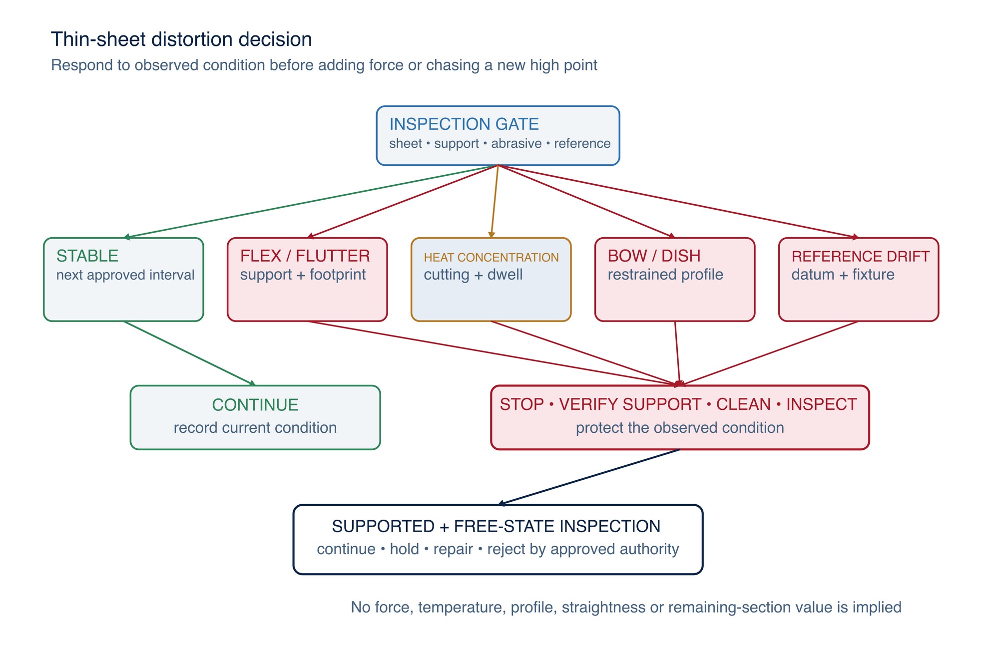
| Signal | Possible system cause | Controlled response |
|---|---|---|
| Sheet flexes or oil-cans under the product footprint or pressure | Unsupported span, point support, excessive pressure | Stop; inspect both faces and verify the fixture and product system before continuing |
| Local heat rises but removal slows | Rubbing, loading, glazing, dwell or unsuitable product | Stop; clean, inspect and correct the system—do not add pressure |
| Panel bows or dishes while clamped | Uneven heat/removal, fixture movement or restraint change | Stop; preserve the fixture condition and obtain profile disposition |
| Shape changes after unclamping | Released residual stress or the fixture concealed distortion | Record the free-state result; do not force flat or grind the new high point automatically |
| Edge, hole or formed feature loses reference | Footprint crossed the boundary, support moved or datum was inadequate | Stop immediately; measure the feature and obtain disposition |
| Weld line becomes locally low | Dwell, excessive removal, hidden weld irregularity or deflection during grinding | Hold; verify remaining section, weld quality and repair authority |
| Surface ripples or shows alternating highs and lows | Repeated short strokes, unstable support, pass overlap or sheet vibration | Stop; inspect profile across the full affected span and reassess sequence |
| Unexpected line, cavity, colour change or contamination appears | Pre-existing indication, process damage, coating issue or mixed-material contamination | Stop, segregate and route through the specified inspection or material-control plan |
Controlled thin-sheet workflow
- Identify the component, material, thickness, weld or surface condition and traceability.
- Confirm the authorised removal, protected section, finished profile, surface requirement and acceptance route.
- Review the welding sequence, residual-stress or distortion-control plan, fixture plan and inspection hold points.
- Record the starting supported and free-state profile where required.
- Select and record the exact machine, guard, handles, abrasive, support element, working face and work-support system.
- Verify speed compatibility, mounting, condition, access, lighting, extraction, dust, sparks and contamination controls.
- Mark high material and protected references where the procedure permits.
- Validate pressure response, footprint, pass direction, distributed sequence and cooling/inspection criteria on representative work.
- Grind only authorised high material using the approved sequence without dwell or sustained deflection.
- Stop, clean, inspect, cool and re-reference at each condition-based gate.
- Hold for movement, heat concentration, unexpected indications, loss of section, reference drift or any unsupported result.
- Complete supported and free-state profile, weld, surface and remaining-section inspection; record disposition and release.
Applying thin-sheet grinding guidance
Establish the required profile, remaining section and free-state dimensional condition before grinding. Support the sheet close enough to the work zone to control movement without concealing distortion. Use a product and contact system that provide controllable removal, then apply short, distributed passes with frequent inspection rather than prolonged local dwell.
Check both the supported and released condition where clamping can mask movement. Stop on rapid temperature rise, oil-canning, edge draw, loss of flatness, unexpected weld indications or remaining-section concern. Refer to the product label, Technical Data Sheet, or MKTECH representative.
Thin-sheet grinding record
For repeatability, record the component, material and nominal thickness; drawing, welding, grinding and inspection revisions; starting weld or surface condition; authorised removal; protected section, features and datum; fixture and support identity; starting supported and free-state profile where required; machine, guard and handles; exact abrasive, support element and batch; speed compatibility; working face; access, extraction and contamination controls; load-control method; pass direction and sequence; cooling and inspection gates; abrasive and sheet-condition observations; clamp changes; unexpected indications; remaining section; weld, profile, dimensional and finish results; final supported and free-state condition; and disposition.
Grinding Tube, Pipe and Curved Surfaces
The next chapter, Grinding Tube, Pipe and Curved Surfaces, follows on the following pages of the printed handbook (page 128), outside this chapter extract.