
Production engineers, supervisors, cutting and grinding operators, fabricators, maintenance teams, safety personnel, QA/QC personnel, procurement staff, trainers and technical sales personnel
Construction and selection of identified bonded cutting-off wheels by type, thickness, diameter, bore, grain, bond, fillers, reinforcement, marked maximum speed, material declaration and stainless compatibility. Cutting speed, expected kerf, edge quality and burr level are treated as controlled trial outputs. This chapter does not prescribe an MKTECH product, wheel size, grain, bond, reinforcement, bore, machine, RPM, peripheral speed, feed, force, cut time, kerf, burr or edge-acceptance value.
A cutting wheel is a high-speed bonded tool, not a thin grinding disc. Use only an undamaged, identifiable wheel whose declared cutting use, type, dimensions, bore, reinforcement, material suitability, expiry where applicable and marked maximum operating speed match the current machine, guard, spindle, flanges and instructions. Never alter the bore, force the wheel onto the spindle, exceed its marked maximum speed or use the side of a cutting-only wheel for grinding. Stop for missing or contradictory marking, damage, distortion, moisture, incorrect fit, abnormal vibration, edge breakdown, binding, heat, loss of control or an unapproved material/application. [S032; S063; S090–S092; S095]
Chapter objectives
After this chapter, the reader should be able to:
- read a cutting wheel as one complete controlled identity;
- distinguish type 41 flat and type 42 depressed-centre constructions;
- explain how thickness, diameter and bore affect selection without using them as shortcuts;
- explain how grain, grit, bond, fillers and reinforcement work together;
- verify material and stainless compatibility from the exact product declaration;
- separate wheel maximum RPM, peripheral speed and cutting progress;
- treat expected kerf, edge quality and burr as measured trial outputs;
- compare candidate wheels using a controlled cut-quality record;
- recognise selection-related warning signals; and
- create a traceable cutting-wheel selection record.
Begin with the cut requirement
“Cutting wheel” describes an operation, not a complete specification. Start by defining what must be separated and what the accepted cut must leave behind.
Record:
- material, grade, coating and contamination restrictions;
- sheet, tube, profile or solid cross-section and the section actually intersected;
- machine type, asset, guard, spindle, flange set and maximum possible speed;
- required access, remaining-wheel clearance and cut depth;
- dimensional allowance and whether the cut is rough, intermediate or final;
- permitted kerf and material loss;
- required squareness, edge profile, heat/discolouration and burr condition;
- downstream welding, machining, coating, cleaning or inspection;
- production quantity and accepted-output target; and
- the current drawing, work instruction, risk controls and acceptance authority.
Do not select by wheel diameter or familiar colour first. The exact wheel must be declared for the material, operation and machine interface, then proven against the required output.
Read the complete wheel identity
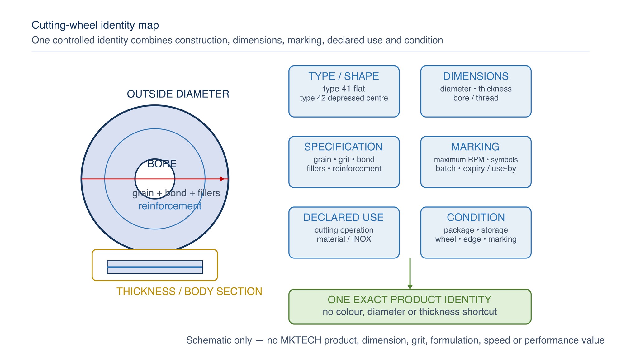
ISO 525:2020 defines the general system of bonded-abrasive shape types, dimensional symbols, specification, designation and marking. ISO 603-16:2022 identifies common nominal dimensions for hand-held type 41 flat and type 42 depressed-centre cutting-off wheels. These standards organise product identity; they do not make two products interchangeable or supply an MKTECH selection. [S088; S089]
A controlled cutting-wheel identity includes:
- manufacturer, product family and exact code;
- type or shape and declared working edge;
- outside diameter, thickness and bore or threaded interface;
- abrasive grain family, grit or manufacturer grade where declared;
- bond system, fillers and reinforcement construction;
- material and application declaration;
- maximum operating speed in RPM and any peripheral-speed marking;
- conformity, restriction and safety symbols;
- batch/lot, expiry or use-by marking where applicable; and
- package, storage and wheel condition.
Colour, label design, thickness or successful past use cannot replace those fields.
Distinguish type, thickness, diameter and bore
| Field | What it changes | Invalid shortcut |
|---|---|---|
| Type or shape | Centre geometry, mounting clearance and declared use | “Any thin wheel is a type 41 cutting wheel” |
| Thickness | Nominal body width, lateral stiffness, clearance and material engaged | “Wheel thickness equals finished kerf” |
| Outside diameter | Machine and guard fit, available depth, peripheral speed and changing clearance as the wheel wears | “A smaller wheel is always safer or interchangeable” |
| Bore or thread | Spindle and flange interface, centring and clamping arrangement | “If it enters the spindle, it fits” |
Type 41 is a flat cutting-off form. Type 42 is a depressed-centre cutting-off form. A product intended for combined cutting and grinding is a separate declared construction; reinforcement or a depressed centre does not by itself authorise side grinding. [S088; S091; S092]
Thickness
Thickness is a construction field and a trial variable. Manufacturer catalogues often position thinner wheels for narrow cuts, low material loss or reduced burr, but those are product-specific claims. A thinner wheel may offer lower nominal material engagement, while a thicker wheel may offer different stiffness or durability. Neither tendency approves a wheel for the machine or predicts the accepted edge. [S093]
Actual kerf can be wider than nominal wheel thickness because the wheel, machine and work form a dynamic system. Run-out, flange condition, wheel deflection, side motion, wear, cut length, work movement, material response and loss of line control can all widen or vary the cut. Measure kerf on representative work.
Diameter
Diameter must match the machine capacity, guard and mounting system. It also participates in peripheral speed at a given RPM and controls available reach. As a consumable wheel wears, remaining diameter, clearance and machine response change; the acceptable replacement point comes from the exact product and machine instructions, not from fitting a worn large wheel to a faster small machine.
Bore
The bore must fit freely on the intended spindle and work with the correct, clean, undamaged flange set. Do not enlarge, drill, file or force a bore. Do not improvise washers, bushings, flanges or adapters. OSHA requires speed verification, free fit and clean, flat contact surfaces; any bushing must not interfere with the flanges. [S095]
Grain, grit, bond, fillers and reinforcement work together
The abrasive grain cuts, but cutting behaviour is not determined by grain name alone. Grit size and shape, the grain blend, bond chemistry, fillers, reinforcement, wheel density and the bond–grain interface all influence cutting action, wear, heat and stability.
A peer-reviewed cut-off-wheel study states that cutting properties depend on abrasive properties together with the bonding agent, fillers and reinforcement fabric. Its experimental wheel results are not transferable, but the construction principle is important: changing one field can change the complete response. [S094]
General screening questions include:
- Is the grain and complete formulation declared for the work material?
- Does the product specification favour the required cross-section and duty?
- Is the bond intended to release or retain grain appropriately in that application?
- Do fillers support the declared cutting behaviour and material restrictions?
- Is the reinforcement construction declared for the machine and wheel type?
- Does the wheel remain stable without glazing, rapid wear, edge crumbling or abnormal heat?
Do not convert a grain abbreviation, grit number or reinforcement layer count into a universal performance ranking.
Reinforcement does not remove the lateral-load limit
Reinforcement is an engineered component of many resin-bonded cutting wheels. It contributes to the declared construction and safety performance, but it does not turn a cutting-only wheel into a grinding wheel.
Reinforcement does not convert a cutting wheel into a side-grinding wheel: the declared wheel edge is the working zone for cutting. FEPA distinguishes flat and depressed-centre cutting wheels and addresses fitting, guarding and condition. oSa notes that even a slight tilt or curved cut can create large lateral loads on a wheel approved only for straight cuts. [S091; S092]
Selection must therefore preserve the declared use:
- cutting-only wheel: use only for the declared cutting operation;
- combined cut-and-grind wheel: verify that exact combined declaration and all machine requirements;
- stationary or mobile saw wheel: verify the separate machine, mounting and operating standard; and
- non-reinforced wheel: use only where the manufacturer and machine specifically permit it.
Chapter 019 will address correct cutting technique. This chapter establishes only the product-use boundary.
Verify material and stainless compatibility
Material compatibility is an exact product declaration. Do not infer it from wheel colour, a generic aluminium-oxide label or successful use on another metal.
For stainless steel:
- obtain the exact wheel manufacturer’s stainless or INOX declaration;
- verify any controlled iron, sulfur and chlorine limits from the current TDS;
- segregate the wheel, flanges, supports and cleaning tools where the process requires stainless-only use;
- prevent cross-use on carbon steel when contamination controls prohibit it;
- confirm compatibility with the stainless grade, cross-section and downstream service; and
- record the product document revision and batch/lot.
A stainless-suitability or INOX declaration belongs to the exact product and may be supported by controlled impurity limits. Never generalise that declaration to another wheel with similar colour, dimensions or appearance. [S092]
For aluminium, non-ferrous alloys, cast iron, nickel alloys, coated materials and mineral products, obtain the exact material and application declaration and assess loading, heat, dust, fire, coating and contamination hazards separately.
Maximum RPM is a compatibility ceiling
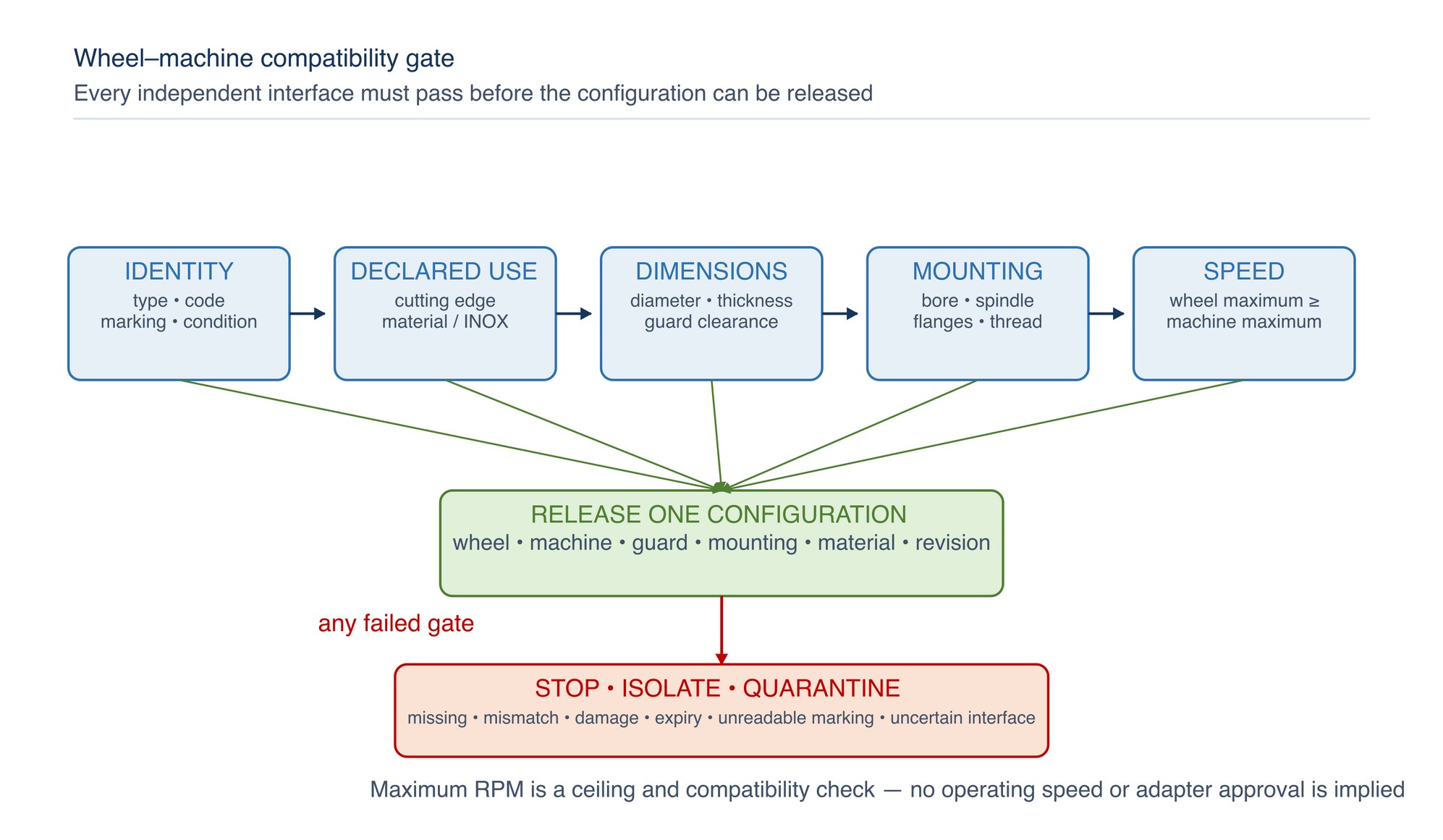
The wheel’s marked maximum operating speed must be equal to or greater than the machine’s maximum possible speed for the fitted configuration. Compare maximum with maximum; do not rely on typical loaded speed, operator habit or an assumed variable-speed setting.
The speed gate also includes:
- exact wheel diameter and type;
- machine model and declared capacity;
- guard type and size;
- spindle, bore, thread and flange compatibility;
- machine condition and speed-control integrity; and
- wheel marking, condition and expiry where applicable.
OSHA requires the machine spindle speed to be checked against the wheel marking before mounting. CCOHS and FEPA repeat the same essential compatibility principle. [S090; S091; S095]
Separate RPM, peripheral speed and cutting progress
“Cutting speed” can mean different things and must be labelled.
- Machine or wheel RPM is rotational speed.
- Peripheral speed is the linear speed at the wheel circumference and depends on diameter and RPM.
- Cutting progress is how quickly the wheel advances through the work or completes a defined cut.
- Production rate is accepted cuts or components per unit time, including changeover and rework.
The wheel maximum RPM or peripheral-speed marking is a limit, not proof of the best cutting condition. Cutting progress also depends on material, section, wheel construction, available machine power, wheel wear, work stability and the approved technique. Do not increase speed, force or feed to meet a time target unless the exact system permits it and the trial remains within safety and quality controls.
Record these quantities separately so “faster” cannot hide a speed violation, wider kerf, excessive burr, heat, wheel wear or rejected parts.
Treat kerf, edge quality and burr as outputs
Nominal thickness helps form a hypothesis; the controlled trial establishes the output.
| Trial output | What to record | Why wheel specification alone is insufficient |
|---|---|---|
| Cut time and production rate | Time for the defined cut, interruptions, changes and accepted parts | Material, cross-section, machine response, wheel wear and technique interact |
| Kerf | Width and consistency at declared locations, material loss and variation through the cut | Thickness, run-out, deflection, side motion, wear and work movement interact |
| Edge geometry | Squareness, straightness, profile, breakout, rounding and remaining allowance | Wheel stability, mounting, access, material and cut path interact |
| Burr | Location, direction, continuity, height or approved rating and removal requirement | Ductility, section, wheel response, exit condition and support interact |
| Thermal condition | Discolouration, recast/smear, coating damage and temperature checks specified by the plan | Cutting action, loading, contact time, material and heat flow interact |
| Wheel condition | Diameter loss, edge condition, glazing, loading, cracking, chipping and balance | Bond, grit, reinforcement, duty and misuse interact |
Thin cutting wheels may be intended to reduce kerf, material loss or burr under stated application conditions. Define how kerf, edge quality and burr will be measured, then compare the exact wheel-machine-material combination on representative work. [S093]
Do not call an edge “burr-free” merely because no large burr is visible. Inspect the complete circumference or profile under the declared method, and account for any downstream deburring, welding, cleaning or machining.
Compare candidate wheels fairly
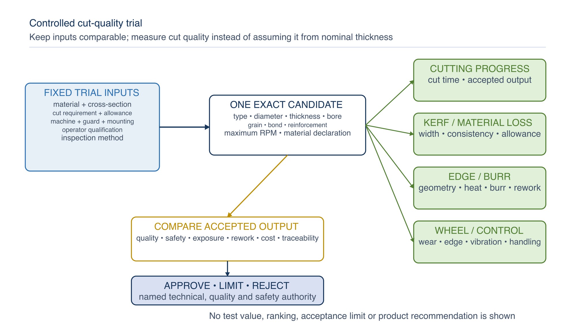
A comparative trial changes one controlled candidate at a time while keeping the work definition, machine, mounting, guard, operator qualification, acceptance method and recording method consistent.
For every candidate, record:
- exact product, code, batch and document revision;
- type, diameter, thickness, bore, grain, grit, bond, reinforcement and maximum speed;
- material declaration and stainless-control status;
- machine, guard, spindle, flanges and maximum possible speed;
- starting and ending wheel condition and diameter;
- number and cross-section of accepted cuts;
- cut time, interruptions and changeover;
- measured kerf and material loss;
- edge geometry, heat/discolouration and burr;
- dust, spark, noise, vibration and operator-control observations;
- downstream deburring, grinding, cleaning or rework; and
- acceptance, rejection, limitation and approver.
Compare cost per accepted output, not wheel price or fastest single cut. A candidate that cuts quickly but produces variable kerf, heavy burr, heat damage, rapid wear or rework is not automatically the better system. [S036]
Selection-related warning signals
| Signal | Possible selection or compatibility cause | Controlled response |
|---|---|---|
| Wheel will not cut or glazes | Wrong material declaration, unsuitable grain/bond, loading, worn wheel or inadequate machine response | Stop; verify the complete product–machine–material specification |
| Rapid wheel wear | Unsuitable bond/duty, excessive load, speed response, unstable work or damaged wheel | Hold output; inspect wheel, machine and cut record |
| Edge crumbles or wheel chips | Side load, binding, incorrect flange, damage, work movement or unsuitable construction | Stop immediately; isolate the machine and quarantine the wheel |
| Kerf is wide, tapered or inconsistent | Run-out, flange/spindle condition, wheel deflection, wear, work movement or path instability | Stop; inspect the complete system before further cutting |
| Heavy or variable burr | Unsuitable wheel/section combination, changing wheel condition, work movement or unqualified process | Measure the burr and revalidate candidate selection |
| Blue, smeared or heat-damaged edge | Loading, rubbing, unsuitable construction, poor cutting progress or excessive heat input | Stop; protect the part and obtain material/quality disposition |
| Vibration or abnormal sound | Wheel damage, imbalance, incorrect fit, dirty or damaged flanges, machine defect or binding | Make safe; quarantine the wheel and inspect the machine |
| Rust staining or contamination concern | Wrong material declaration or mixed-metal product/tool history | Segregate, preserve evidence and follow the stainless disposition |
Do not respond by adding uncontrolled force, exceeding marked speed, dressing the wheel by improvised contact or using the side of a cutting-only wheel.
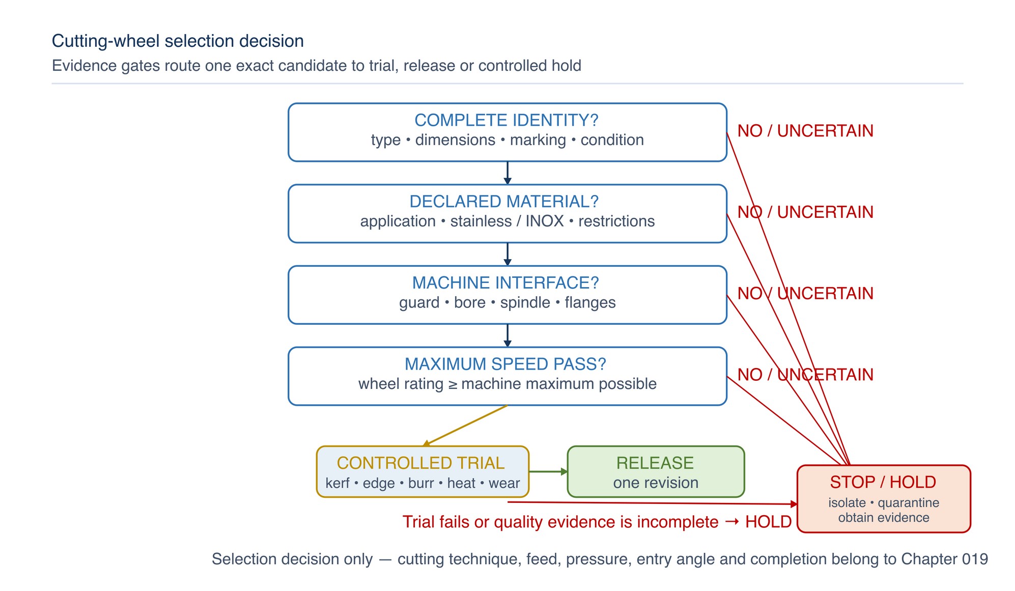
Controlled selection workflow
- Define material, cross-section, quantity, downstream process and accepted cut.
- Identify the exact machine, guard, spindle, flange set and maximum possible speed.
- Select only a wheel type declared for the cutting operation and machine class.
- Verify diameter, thickness, bore and mounting interface.
- Verify grain, grit, bond, fillers and reinforcement from the current product data.
- Verify material and stainless compatibility, segregation and contamination controls.
- Verify the wheel maximum operating speed against the machine maximum possible speed.
- Verify conformity, restrictions, expiry where applicable, batch and condition.
- Define measurable cut-time, kerf, edge, burr, heat, wear and control criteria.
- Run a representative controlled trial under the approved Chapter 019 technique.
- Compare accepted output, wheel condition, rework, exposure and cost.
- Release one exact wheel–machine–material–cut requirement revision or hold the decision.
Selecting a cutting wheel in practice
Start with the work material, section geometry, cut quality and downstream operation. Read the complete wheel marking and confirm type, diameter, thickness, bore, declared application, reinforcement, maximum permitted speed and expiry or use-by information. Match the wheel to the machine, guard, spindle and flanges without improvised adapters.
Thinner wheels can reduce kerf and cutting force but demand accurate alignment and strong control against side loading; thicker wheels may provide greater robustness but remove more material. Compare candidates by straightness, squareness, burr, heat, wheel condition and accepted output—not speed or wheel life alone. Refer to the product label, Technical Data Sheet, or MKTECH representative.
Cutting-wheel selection record
For repeatability, record the task, component, material and grade, coating, cross-section, quantity, downstream process, drawing and acceptance criteria, machine or asset, guard, spindle, flanges, machine maximum speed, wheel manufacturer, family, code, batch or lot, type, diameter, thickness, bore or thread, grain, grit, bond, fillers, reinforcement, maximum-speed marking, material declaration, conformity and expiry marking, storage condition, cutting method, cut time, kerf, edge geometry, burr, heat or discolouration, wheel wear, exposure observations, rework, accepted output and cost basis.
Correct Cutting Technique
Correct cutting technique is presented in Chapter 019 of the printed handbook, outside this chapter extract.