
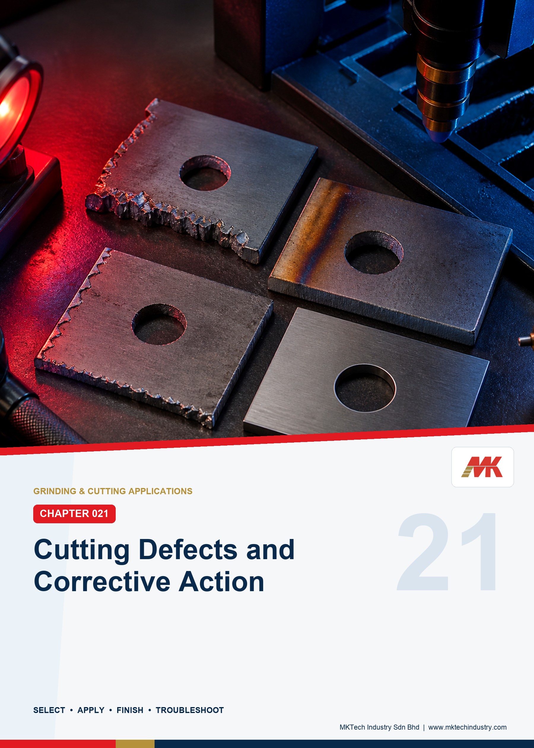
Production engineers, supervisors, cutting and grinding operators, fabricators, maintenance teams, safety personnel, QA/QC personnel, trainers and technical sales personnel
Troubleshooting abrasive cutting-off with a hand-held angle grinder and an identified bonded cutting wheel. It covers slow cutting, wheel breakage, burnt edges, excessive burr, wandering cuts, chipping, glazing, premature wear, vibration and wheel pinching. Chapters 018–020 remain mandatory for selection, technique and geometry control.
Wheel breakage, cracking, edge loss, wheel pinching, abnormal vibration, loss of control, guard contact, machine damage, unexpected work movement or a slowing/stalling machine requires immediate release of the switch and controlled coastdown. Hold the tool motionless until the wheel stops; do not restart in the cut or attempt to free, dress, grind or reuse a suspect cutting wheel. Isolate the machine, control the hot and sharp work, preserve relevant evidence, and investigate before any representative trial. Never correct slow cutting by forcing the wheel, side loading it, increasing speed beyond a rating, removing the guard or fitting an unapproved product. [S032; S090–S091; S095; S097–S098; S103–S104]
Chapter objectives
After this chapter, the reader should be able to:
- separate an observed defect from its possible causes;
- classify a condition as safety-critical, quality-critical or process-performance related;
- apply a stop, contain, inspect, correct, trial and release workflow;
- diagnose all ten specified cutting defects without changing several variables at once;
- protect wheel, machine, workpiece and setup evidence after abnormal events;
- choose corrective actions at the correct level of the cutting system;
- define a representative verification trial and acceptance record; and
- use established industrial practice while taking exact settings and acceptance values from current product and job information.
A symptom is not a root cause
“The wheel is slow,” “the edge is blue,” or “the cut wandered” describes an observation. It does not identify why the observation occurred. One symptom may arise from several mechanisms, and one mechanism may create several symptoms.
For example, slow cutting may be associated with a wheel that is unsuitable for the material or section, a glazed or loaded cutting edge, inadequate machine power, speed loss under load, excessive engagement, poor access, a closing kerf or an operator forcing an unstable system. The same speed loss can increase rubbing and heat, encourage more pressure, accelerate wander and raise breakage risk. Manufacturer troubleshooting information recognises links among wheel hardness or thickness, peripheral speed, machine power, pressure, movement and side force; those links are diagnostic prompts, not permission to change an unidentified system. [S080; S090; S094; S103]
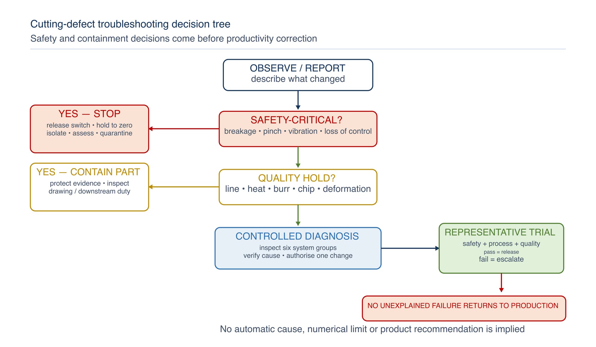
Use three defect classes:
- Safety-critical: wheel breakage or damage, pinching, severe or new vibration, guard/flange contact, machine damage, loss of control, unexpected work movement or repeated stall.
- Quality-critical: cut outside drawing limits, burnt or contamination-sensitive edge, excessive burr, chipping, breakout, unacceptable wander, deformation or insufficient downstream allowance.
- Performance-related: slower-than-qualified cutting, glazing, loading or premature wear when no safety or quality hold is present.
A performance symptom becomes safety-critical when it leads to force, overload, side loading, heat, unstable contact or loss of control.
The controlled troubleshooting method
Apply this sequence to every defect:
- Stop safely. Release the switch, maintain control, and wait for zero rotation. Follow the machine manual for binding or interrupted cuts.
- Contain. Prevent access, movement, re-energisation, reuse of a suspect wheel, loss of fragments and accidental release of a nonconforming part.
- Describe the symptom. Record what was seen, heard, felt and measured; identify when and where it began.
- Protect evidence. Keep the wheel identity, batch, machine, guard, flanges, workpiece, off-cut, supports and relevant fragments available for examination.
- Inspect by system. Check work/material, wheel, machine/mounting, support/geometry, technique and environment.
- Test the cause. Change only a verified or strongly evidenced cause through an authorised action. Do not tune around damage.
- Run a representative trial. Use the exact proposed system on representative work under controlled conditions.
- Inspect the output. Compare line, squareness, burr, heat, chipping, deformation, contamination, wheel condition, time and machine response with the approved criteria.
- Release or escalate. Record the decision and approvers. Repeat failure, unexplained damage or inconsistent output remains on hold.
This method prevents “trial-and-error” changes that conceal the cause. It also separates three controls: current manufacturer instructions define product and machine limits; the drawing or customer specification defines output acceptance; and a representative verification confirms that the complete combination is repeatable. [S036; S090–S091; S097–S098]
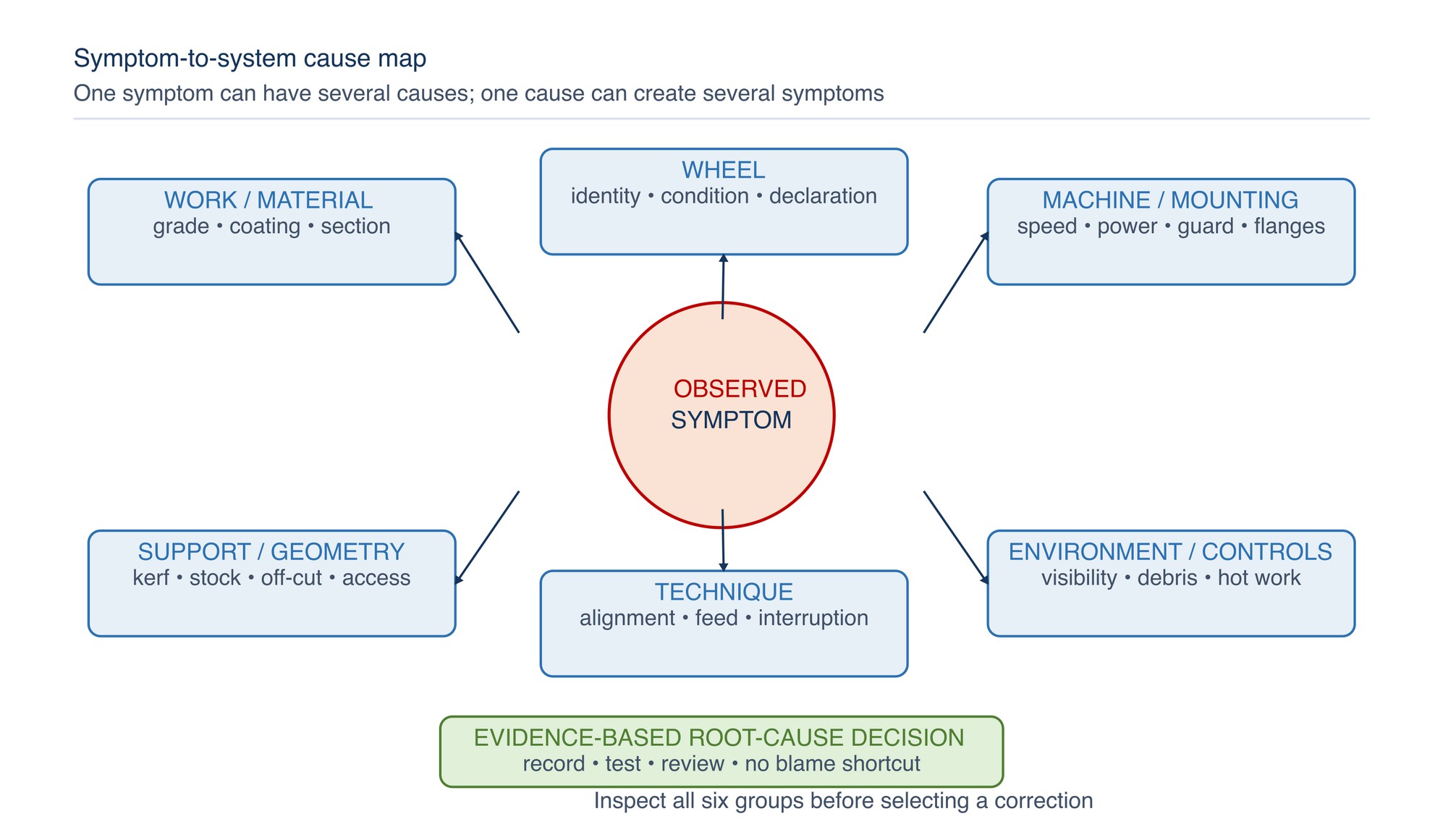
Inspect the six parts of the cutting system
Before choosing a corrective action, inspect all six groups:
- Work and material: grade, coating, hardness/condition, cross-section, wall, seam, contamination, temperature, residual stress and downstream requirement.
- Wheel: manufacturer, family, code, type, dimensions, declaration, maximum speed, expiry, storage history, batch, edge condition, glazing, loading, wear and damage.
- Machine and mounting: asset, current manual, rated/no-load speed, power supply or air condition, guard, handles, spindle, flanges, threads, runout, bearings and maintenance status.
- Support and geometry: datum, line transfer, access, retained stock, off-cut, kerf movement, clamp security, distortion, final ligament and wheel clearance.
- Technique: alignment, entry, contact, travel direction, feed, interruption, re-entry, indexing, side loading and forcing.
- Environment and controls: hot work, extraction, debris, lighting, visibility, footing, cable/hose routing and contamination segregation.
Do not assume that a new wheel corrects a support problem, that more power corrects a wrong product, or that deburring corrects an out-of-position cut.
Slow cutting
Recognise it. Cutting time rises against the approved baseline; progress slows while contact continues; sparks or motor response change; the operator is tempted to press harder; or the wheel rubs without stable material removal.
Stop and inspect. Check for glazing or loading, an incorrect material declaration, unsuitable wheel construction or thickness, speed loss under load, inadequate power supply, excessive engagement, guard or flange contact, a closing kerf, poor access, work movement and forced technique. CCOHS explicitly warns against forcing a cut until the motor slows. HSE warns that selecting for long wheel life rather than cutting efficiency can reduce abrasiveness, increase time and tempt excessive pressure, distortion, vibration and breakage. [S080; S090]
Correct. Restore support and a neutral/open kerf; repair an approved machine or supply fault; replace a damaged, loaded or unsuitable wheel with an exact declared product selected under Chapter 018; and repeat the qualified Chapter 019 technique. A manufacturer may recommend a different grade, thickness or speed within a named product system, but only that manufacturer’s current instructions and a controlled trial can authorise the change. Do not add force or exceed either rating. [S090; S097; S103]
Verify. Record cut time, machine response, wheel condition, edge heat, burr and dimensional output together. A faster cut that creates unsafe vibration, damage or rejected edges is not a correction.
Wheel breakage, cracks and edge loss
Wheel breakage is an incident, not a productivity defect. It may involve full fracture, centre or arbor-hole breakout, radial cracking, missing edge, crumpled edge, delamination or unexplained fragment loss.
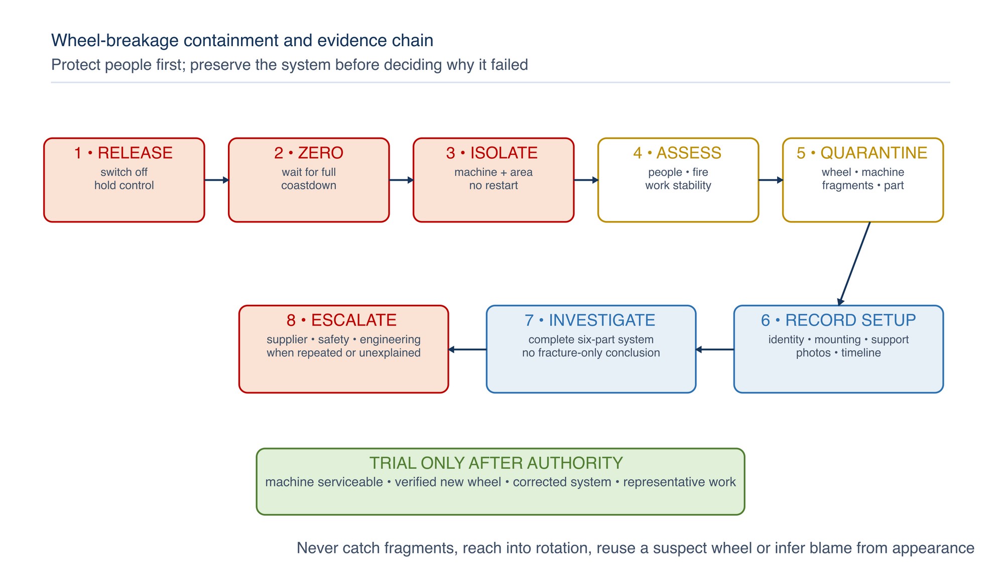
Immediate response:
- release the switch and maintain the safest available control position;
- do not reach toward the rotating system or attempt to stop it with side pressure;
- isolate the machine after coastdown and apply the workplace incident response;
- assess injury, fire, secondary damage and the stability of stock and off-cut;
- quarantine the machine, wheel, packaging/label, flanges and retrievable fragments;
- record photographs and orientation before disturbing the setup where safe; and
- prevent reuse or informal disposal until the investigation authority releases the evidence.
Possible mechanisms include prior impact or poor storage, expired or unidentified product, wrong wheel or mounting, mismatched/damaged/dirty flanges, excessive tightening, overspeed, guard or component contact, grinding on a cut-off wheel, side pressure, twist, work movement, pinching, a closing kerf, uncontrolled breakthrough, machine defect or repeated stall. FEPA requires careful pre-fit examination and destruction/disposal of damaged wheels; CCOHS prohibits cracked or damaged wheels, unequal or damaged mounting surfaces, side grinding, jamming, bending, pinching and forced slowdown. [S090–S091]
Do not decide from fracture appearance alone that an operator, wheel or machine was at fault. A competent investigation must reconcile evidence from the complete system and the event sequence. Repeated or unexplained breakage requires supplier/manufacturer and safety escalation before another trial.
Burnt edges and heat damage
Burnt edges may appear as heat tint, oxide, coating damage, blackening, smearing, local melting, loss of edge definition or heat-related distortion. Appearance alone does not prove material condition or acceptability.
Possible contributors include a glazed or loaded wheel, unsuitable wheel/product, prolonged dwell, excessive engagement, forced feed, speed loss, repeated passes, poor support, a closing kerf, an inappropriate process for thin or coated work, and material-specific contamination or loading. [S004; S016; S080; S090; S103]
Corrective route: hold the part; record the location and extent; identify the material, coating and downstream duty; inspect wheel, machine response, support, engagement and technique; correct the verified mechanism; then trial on representative material. The drawing, welding procedure, coating specification or customer acceptance plan decides whether the edge may be cleaned, reworked, machined, cut back or rejected. Do not remove colour before the evidence and disposition are recorded. For stainless steel, a visually cleaned edge is not automatically corrosion-ready or weld-ready. For coated work, lost coating requires the specified repair route. [S004; S021; S028]
Excessive burr
A burr is displaced or attached material at the exit edge or along the cut. Record its location, continuity, direction, sharpness and any associated rollover, tear, heat or deformation. Do not use “low burr” or “burr-free” as a generic promise: product claims apply only to identified products and conditions. [S093]
Investigate wheel suitability and condition, cut direction under the machine manual, exit support, final-ligament behaviour, section vibration, line angle, heat, material smearing, wheel wear and whether the abrasive method is appropriate for the required edge. An excessive burr may accompany slow cutting, loading, poor support, unstable breakthrough or a cut outside the intended plane.
Correct the cause before specifying deburring. Deburring is a downstream operation; it does not make an incorrect line, heat-damaged edge, thin wall, contaminated stainless surface or unsafe fracture acceptable. Verify the cut and the subsequent edge preparation against drawing allowance, minimum thickness, edge radius/chamfer and downstream welding or coating requirements.
Wandering or out-of-line cut
Wander is deviation of the kerf from the intended cut plane. It may appear as curvature, taper, a stepped join between faces, loss of squareness or a second corrective kerf.
Inspect line transfer, visibility, datum, work movement, machine alignment, wheel plane, guard/handle clearance, wheel damage or excessive wear, side loading, deep unsupported engagement, operator stance and whether the geometry can be reached while guarded. Pinching and sudden changes in engagement may also pull the system away from the line. [S097]
Stop before the operator tries to steer the wheel by twisting or side pressure. If enough allowance remains and an approved rework can restore the part without violating section, heat or downstream requirements, disposition it through QA. Otherwise reject or escalate. The prevention is a complete datum line, stable support, accessible one-plane path, full-stop re-clamping between faces and a representative trial—not a stronger grip on an unsuitable setup.
Chipping, breakout and ragged edges
Chipping may describe loss from the wheel edge or breakout from the workpiece. Record which one occurred.
- Wheel-edge chipping: treat as suspect wheel damage. Stop, isolate and investigate product condition, contact impact, side load, pinch, mounting, guard contact, work movement and breakthrough. Do not continue until an authorised inspection determines the machine and mounting are serviceable and a new verified wheel is fitted.
- Workpiece breakout: hold the part and inspect material/coating condition, exit support, final ligament, engagement, vibration, line and process suitability. Brittle coatings, cast features, thin edges or interrupted sections may require a different support, sequence or cutting process.
Never smooth away wheel damage or use the side of a cutting wheel to blend a chipped work edge. [S090–S092; S097]
Glazing and loading
Glazing is a cutting surface that has become smooth or shiny because effective cutting edges are not renewing as required. Loading is work material or debris adhering to and blocking the cutting surface. They are different observations but both can reduce cutting action and increase heat.
Check product suitability for the material, wheel condition, material transfer, storage history, contact and engagement, speed loss, heat, technique and the manufacturer’s declared remedy. Aluminium and other non-ferrous materials require a product explicitly declared for that application; do not assume a steel or stainless wheel is suitable. [S005; S080; S093]
Do not dress a reinforced cutting wheel, scrape loading away, apply lubricant/coolant or alter speed unless the exact current wheel and machine instructions expressly authorise the action. The safe default for an unidentified, damaged or persistently loaded/glazed cutting wheel is removal from service and replacement with a verified suitable product.
Premature wheel wear
Premature wear means the wheel consumption is greater than the approved reference for the same controlled system and acceptable output. A short life by itself does not prove a defective wheel.
Inspect material and section, wheel grade/construction and dimensions, machine speed and power, contact duration, excessive force, repeated starts, deep engagement, work movement, side pressure, pinching, heat, storage and batch identity. Manufacturer troubleshooting guidance links excessive wear to wheel selection, operating speed and speed reduction under load, but any grade or speed change remains product-specific and must stay within the marked ratings and machine instructions. [S094; S103]
Compare wear with cut time, burr, heat and dimensional quality. Selecting only for maximum life can reduce cutting efficiency and encourage unsafe pressure; selecting only for speed can increase cost or fail the quality requirement. [S080]
Vibration and unstable cutting
New, increasing or unusual vibration is a stop signal. Possible causes include wheel damage, poor mounting, damaged or dirty flanges, spindle/bearing condition, work movement, poor support, wheel/work mismatch, unequal wear, resonance, side loading, pinching, guard contact and inappropriate machine capacity.
Do not “cut through” vibration or use hand force to suppress it. After coastdown, quarantine a suspect wheel and inspect the machine, mounting and work support. A wheel that was dropped, struck, cracked, chipped, wet/damaged or involved in a pinch is not returned to service. FEPA requires careful handling and pre-fit inspection; CCOHS requires clean, flat mounting surfaces and prohibits damaged wheels and misuse. [S090–S091]
If vibration persists with a verified new wheel and corrected support, remove the machine from service for competent inspection. Repeated vibration may indicate a machine, mounting, fixture or system issue rather than a consumable issue.
Wheel pinching and binding
Pinching occurs when the work closes on, traps or laterally loads the wheel. Binding may also occur when the wheel is misaligned, twisted, forced, driven into an unstable section or caught by off-cut movement.
Release the switch and hold the tool motionless until the wheel stops, following the current machine manual. Do not restart while trapped. Do not pull a rotating bound wheel from the kerf. After stop, isolate the tool, secure both portions, relieve the load by an engineered work-support method that does not expose people to stored energy, and inspect wheel, machine and kerf. [S090; S097]
Correct the support arrangement so the kerf opens or remains neutral; control stock and off-cut through the final ligament; restore one-plane alignment; and use a different machine or fixture if guarded reach or geometry cannot be maintained. Any wheel exposed to damage, side load or uncertain pinch history is removed from service.
Defect interaction map
The ten symptoms often form a feedback loop:
- unsuitable or degraded cutting action increases contact time;
- added pressure and speed loss increase heat and instability;
- heat and smearing can increase loading, burr and edge damage;
- instability can increase wander, chipping and pinching;
- pinching or side load can damage or break the wheel; and
- repeated re-cuts increase wear, heat and dimensional loss.
The safe correction breaks the loop at the verified cause. It does not compensate at the next symptom.
Troubleshooting matrix
| Symptom | Immediate response | Plausible mechanisms to inspect evidence | Correction and release |
|---|---|---|---|
| Slow cutting | Stop if response is abnormal or force is increasing | Glazing/loading; wrong declaration; speed/power loss; long engagement; closing kerf; force + wheel condition | Restore support or machine condition; select verified product; trial time + heat + burr |
| Wheel breakage/damage | Stop, isolate, assess injury/fire, quarantine evidence | Impact/storage; expiry; mounting; overspeed; side load; pinch; movement; machine defect | Competent investigation; machine/mount inspection; verified new wheel; authorised representative trial |
| Burnt edge | Hold part and preserve material/drawing condition | Dwell; rubbing; loaded/glazed wheel; force; speed loss; repeated pass; poor process choice | Correct mechanism; disposition representative heat and quality check |
| Excessive burr | Hold sharp part and inspect support/product/process; verify related defects | Exit support; unstable breakthrough; wheel condition; heat/smear; line/angle; wrong process | Correct burr and downstream allowance |
| Wandering cut | Stop; do not steer by twist | Incomplete line; movement; misalignment; side load; poor access; pinch | Restore datum/support/access; QA disposition; trial line and squareness |
| Chipping/breakout | Wheel chip = isolate; work chip = hold part | Wheel damage; impact; pinch; brittle coating/material; unsupported exit | Investigate correct object; replace suspect wheel; verify exit support and part acceptance |
| Glazing/loading | Stop if heat or force rises | Product/material mismatch; dull surface; material transfer; heat; speed loss | Follow exact manufacturer remedy; otherwise replace with verified suitable product |
| Premature wear | Stop if wear is uneven or damage appears | Product mismatch; force; speed/load; repeated contact; pinch; storage/batch | Compare time, wear and quality; approve balanced system, not life alone |
| Vibration | Stop immediately and isolate suspect wheel | Wheel/mount/machine damage; work movement; resonance; side load; pinch | Competent inspection; corrected support; verified new wheel; stable trial |
| Pinching/binding | Release switch; hold to zero; no in-cut restart | Kerf closure; unsupported off-cut; residual stress; twist; unstable final ligament | Secure and unload by engineered method; inspect; redesign support and sequence |
Corrective action and representative verification
One correction record should contain:
- defect ID, part/lot, date, location and reporter;
- photographs, measurements and description before rework;
- wheel manufacturer/family/code/batch, label, expiry and retained condition;
- machine asset, manual revision, guard, handles, spindle, flanges and maintenance state;
- material, form, drawing, datum, support, clamps, sequence and environment;
- event timeline and operator observations without blame language;
- tested mechanism and evidence for the root-cause decision;
- containment and disposition of wheel, machine, part and work in progress;
- one authorised correction and affected documents/training;
- representative trial plan with unchanged and changed variables identified;
- results for safety, machine response, line, squareness, burr, heat, chipping, deformation, contamination, wheel wear and time; and
- engineering, production, quality and safety approval or escalation.
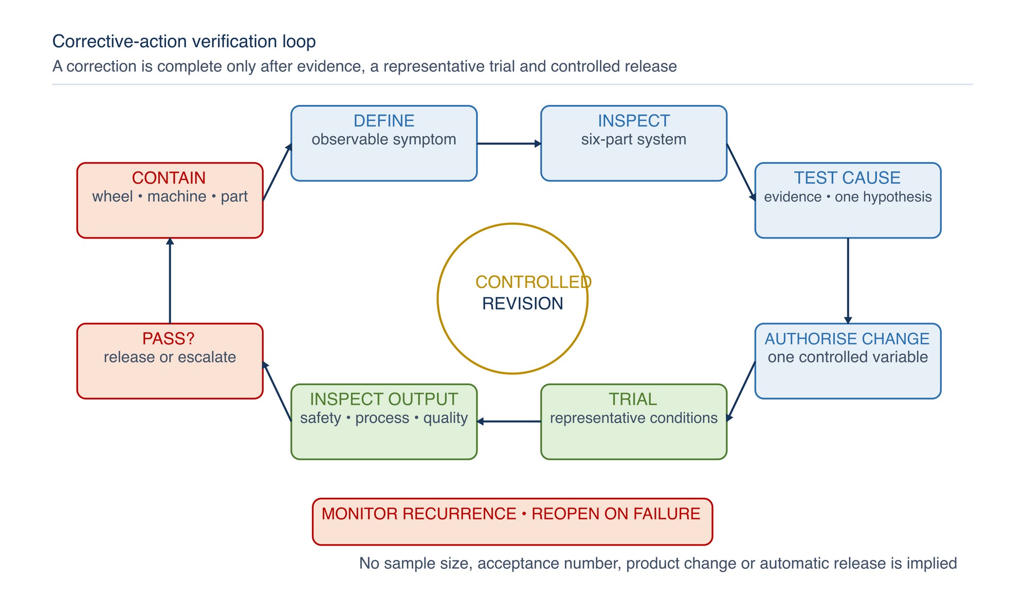
Stop, hold, rework or release
- Stop: active unsafe condition or loss of control; bring the system to zero rotation and isolate.
- Hold: prevent use of a machine, wheel, part, lot or method while evidence and conformity are assessed.
- Rework: use only a documented method that retains required dimensions, material condition, finish, coating, cleanliness and downstream allowance.
- Release: named authority accepts the exact system and output against controlled criteria after representative evidence.
Production pressure, a visually improved edge or one successful cut does not close a corrective action. Repeatability and control of the changed condition are required.
Applying corrective-action guidance
Correct the verified mechanism at the correct level of the system. Restore work support and kerf control before changing a wheel; correct machine or power-supply faults before changing technique; replace damaged or unsuitable wheels rather than increasing force; and use the drawing or customer requirement to decide whether the workpiece may be reworked or must be rejected.
After a change, repeat the cut on representative material and inspect cut time, line, squareness, burr, heat, chipping, wheel condition and downstream allowance together. Never correct a defect by overspeeding, side grinding, removing the guard, forcing the wheel or reusing a suspect product. Follow the current machine instructions. Refer to the product label, Technical Data Sheet, or MKTECH representative.
Surface-Finish Fundamentals
The Surface-Finish Fundamentals chapter begins on the following page of the printed handbook (page 171), outside this chapter extract.