
Production engineers, supervisors, painters, operators, maintenance teams, QA/QC personnel, safety and environmental personnel, procurement staff and technical sales personnel
Practical guidance for selecting, installing, inspecting, changing and disposing of paper labyrinth, expanded-paper, fibreglass, synthetic and multi-layer dry overspray filters used in industrial liquid-paint spray booths.
Never spray with missing, torn, reversed, collapsed or bypassed overspray filters. Keep the filter bank, plenum, duct and fan accessible and free from unsafe residue accumulation. Do not bypass filters or increase fan limits to hide a loaded or unsuitable bank. Keep ignition sources and hot work outside the controlled spray and filter areas. Use the coating SDS, current booth procedure and specified PPE during inspection and change-out. Stop work for smoke, heat, smouldering odour, sudden pressure change, overspray escape or downstream breakthrough. [S175; S185]
Core principle - Match the filter construction to the coating, spray load, booth airflow and downstream protection required. Install the full bank in the correct orientation, seal every edge, and base replacement on verified airflow, pressure trend and loading condition—not appearance or time alone.
An overspray arrestor is the dirty-air filter between the spray zone and the exhaust system. Its primary task is to capture paint droplets and solids before they deposit in the plenum, duct, fan or discharge path. It must perform this task without destabilising the designed booth airflow. A filter that captures well but is overloaded, incorrectly oriented, poorly supported or bypassed at the frame cannot provide reliable system control. [S171; S172; S175; S178]
This chapter addresses dry-filter liquid-coating booths. It does not treat ordinary intake filters as overspray arrestors, and it does not present particulate media as a control for solvent vapours or VOCs. Water-wash systems, powder-recovery systems and specialised emission controls require their own engineered arrangements.
Chapter objectives
After this chapter, the reader should be able to:
- distinguish paper labyrinth, expanded-paper, fibreglass, synthetic and composite overspray-filter constructions;
- explain inertial separation, surface loading and depth loading in practical terms;
- select a media family around droplet character, coating behaviour, spray load and downstream sensitivity;
- recognise when a single-stage or multi-stage system is appropriate;
- install media in the intended airflow direction with continuous sealing and support;
- interpret visible loading together with differential pressure and airflow condition;
- prevent unsafe mixing of incompatible coating residues;
- plan fire-safe filter handling and change-out;
- classify and route used media according to the coating residue and Malaysian waste requirements; and
- troubleshoot premature blocking, breakthrough, bypass, sagging and uneven loading.
Understand what an overspray arrestor controls
Spray application produces droplets with a broad size distribution. Some deposit on the workpiece; the remainder becomes overspray. Larger wet droplets, fine mist, partly dried particles, fibres and coating solids can reach the exhaust face. The filter must retain the intended fraction of that load while allowing the ventilation system to carry air through the booth.
The following four functions should be evaluated together:
| Function | What the filter must do | What to verify in service | Failure symptom |
|---|---|---|---|
| Capture | Remove paint droplets and solids from the exhaust stream | Downstream cleanliness, loading pattern and correct media family | Paint deposits in plenum, duct, fan or discharge |
| Capacity | Store captured material without premature face sealing | Depth of loading, usable surface and change-out trend | Short life, rapid pressure rise or paint run-off |
| Airflow stability | Add predictable resistance within the booth fan duty | Pressure trend, airflow distribution and booth containment | Weak capture, turbulence or overspray escape |
| Mechanical integrity | Remain supported, sealed and correctly oriented | Frame fit, joints, backing, sag and wet strength | Bypass, collapse, tearing or media migration |
Capture efficiency and loading capacity are different properties. A fine stage may capture small particles but block rapidly if it receives the full coarse wet load. A high-capacity first stage may store substantial overspray but still require a downstream polishing stage where the exhaust system or environmental control demands finer capture. Selection therefore starts with the complete filtration duty, not one percentage.
Paper labyrinth filters — separation by direction change
Paper labyrinth filters use punched, pleated or folded paper layers to force the contaminated air through repeated changes in direction. Paint droplets have more inertia than the carrying air. As the air turns through the internal path, droplets tend to continue towards a wall or retention pocket, where they deposit outside the main stream.
The Andreae/AEREM catalogue describes this principle in a two-layer punched and pleated kraft-paper construction. Catalogue variants add paper capacity strips, synthetic backing or glass-fibre backing for different loading and final-capture duties. Treat these as construction families rather than interchangeable grades. Refer to the product label, Technical Data Sheet, or MKTECH representative. [S186; S187]
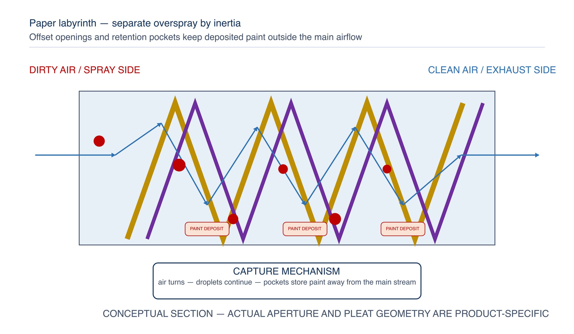
Paper labyrinth media is well suited to applications where wet droplets and useful holding volume favour inertial separation. Its performance depends strongly on correct expansion, orientation and sealing. Under-expansion or over-expansion changes the internal geometry; a reversed filter presents the wrong apertures to the spray side; and a poorly clipped edge creates a bypass path with almost no filtration.
Expanded-paper filters — open area with multiple impaction surfaces
Expanded-paper filters are made by slitting and stretching paper into a three-dimensional mesh or stack. Multiple layers may be offset to create a tortuous route with many impaction surfaces. These filters are generally compact, easy to cut and useful for moderate overspray duties, prefiltration or applications that benefit from a disposable paper construction.
The term “expanded paper” covers different layer counts, paper weights, slit patterns and optional backing media. Two products that look similar may have very different airflow resistance, wet strength, fire behaviour and paint-holding performance. Confirm the intended spray-side orientation and the declared application before installation.
| Paper construction | Capture behaviour | Practical strengths | Selection cautions |
|---|---|---|---|
| Pleated labyrinth | Repeated direction change and retention pockets | Good internal storage; self-supporting accordion form in suitable frames | Must be expanded and oriented as instructed; pocket geometry is product-specific |
| Multi-layer expanded paper | Impaction across offset open layers | Compact, cuttable and adaptable to pads or rolls | Face can seal with sticky paint; layer count alone does not define performance |
| Expanded paper with synthetic backing | Coarse paper stage plus finer fibrous stage | Combines paint storage with improved final capture | Backing adds resistance and must remain on the clean-air side |
| Expanded paper with glass-fibre backing | Coarse inertial stage plus glass-fibre depth stage | Useful where mixed droplet sizes require staged capture | Confirm coating compatibility, handling method and disposal route |
Paper colour is not a universal grade code. Do not select a filter by colour, thickness or visual resemblance. Use the declared construction and application. Refer to the product label, Technical Data Sheet, or MKTECH representative.
Fibreglass paint-stop media — depth loading through an open fibre bed
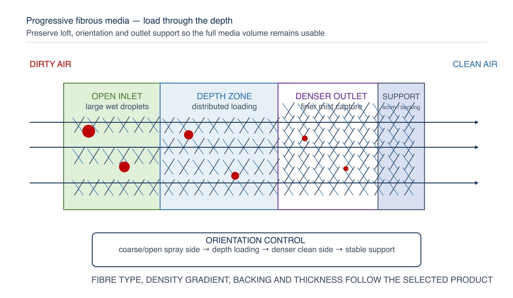
Fibreglass paint-stop media consists of a resilient bed of glass fibres, commonly arranged from a more open spray side towards a denser clean-air side. Overspray collides with fibres and is retained within the depth of the media. The open upstream structure admits wet droplets; the denser downstream region provides progressively finer collection and support.
Fibreglass media is available as rolls or cut pads and can suit general refinishing and industrial liquid-coating duties. It must be handled without compressing the loft, tearing the backing or leaving exposed gaps. Compression reduces the usable depth and can increase resistance; stretching or sagging creates non-uniform flow.
Synthetic media — controlled fibre structure and mechanical stability
Synthetic overspray media commonly uses polyester or another engineered fibre in pads, rolls, pockets or shaped high-surface-area elements. The fibre structure may be progressive, multi-ply, thermally bonded or supported by a scrim. Synthetic media can provide stable handling, consistent thickness and resistance to fibre breakage, but these general characteristics do not establish compatibility with every coating or booth.
Fibreglass and synthetic filters are depth-loading media: particles are collected through a volume rather than only on the front face. Their useful life depends on preserving that volume and presenting the intended coarse-to-fine direction to the airflow.
| Media family | Typical strength | Watch for | Suitable selection question |
|---|---|---|---|
| Fibreglass pad or roll | Open depth and economical general overspray capture | Fibre handling, compression, sag, backing damage and run-off | Is the loft, backing and coating compatibility suitable for the spray load? |
| Synthetic pad or roll | Consistent structure, mechanical resilience and design flexibility | Surface skinning with sticky paint, incorrect orientation and unsupported spans | Does the declared media construction match wet, dry or mixed overspray? |
| Multi-ply synthetic panel | Staged fibre density in a supported format | Higher initial resistance, seal integrity and panel disposal volume | Is the panel intended as the first stage, final stage or both? |
| Pocket, cube or shaped synthetic element | Large effective area and internal storage | Frame depth, airflow distribution, collapse and full seating without bypass | Can the booth accommodate the required depth and support without bypass? |
Multi-layer and high-loading systems
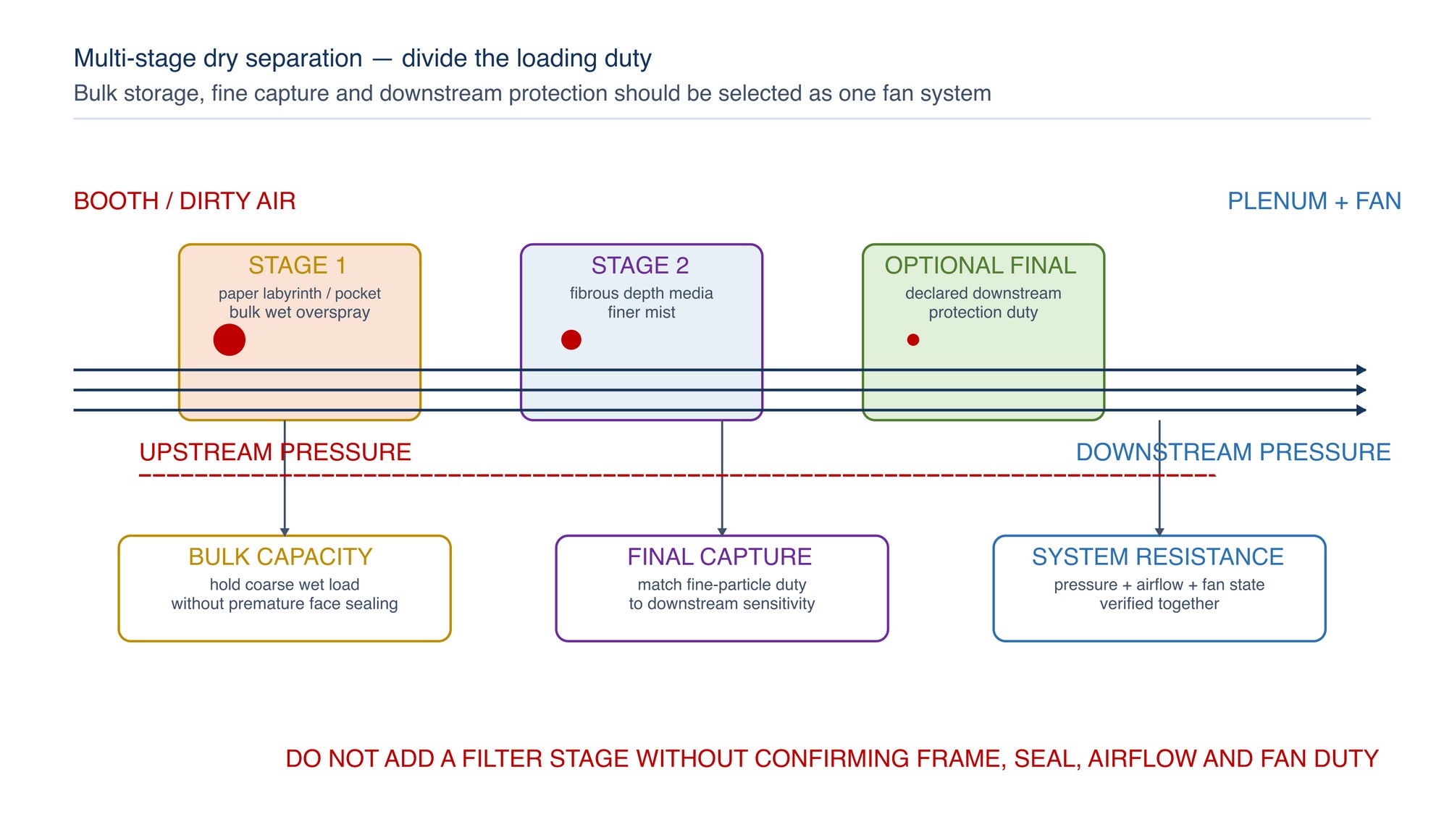
A multi-layer filter combines capture mechanisms or divides the load between separate stages. A coarse paper labyrinth, expanded-paper or deep-pocket stage can remove larger wet droplets and store bulk paint. A downstream fibrous stage then captures the finer mist that passes the first stage. Where required by the engineered exhaust system, a separate final stage protects downstream equipment or supports the specified discharge duty.
High-loading does not mean “leave the filter until airflow fails.” It means the construction is intended to store more paint at an acceptable resistance within its declared operating range. Uneven spraying, a blocked section, paint run-off, damaged media or a fan at its limit can require earlier replacement.
Use multi-stage filtration when one or more of the following conditions apply:
- the spray process produces both heavy wet droplets and fine mist;
- the first-stage face blocks before its internal capacity is used;
- downstream duct, fan or discharge cleanliness requires improved final capture;
- high production loading justifies greater storage volume;
- coating changes cause widely different overspray behaviour; or
- the booth supplier specifies staged protection for the exhaust system.
Adding a stage increases system resistance and may change airflow distribution. Confirm the fan duty, frame depth, seal arrangement and pressure-monitoring method before changing the filtration configuration.
Match filter construction to coating behaviour
Overspray behaviour is influenced by solids content, viscosity, atomisation, transfer efficiency, solvent or water content, cure chemistry, tack time, spray rate and distance to the filter. The same filter may load differently when any of these variables changes.
| Coating or overspray behaviour | Filtration implication | Practical direction |
|---|---|---|
| Large, wet, slow-drying droplets | Needs internal holding volume and resistance to run-off | Favour a high-capacity inertial or open-depth first stage with suitable wet strength |
| Fine atomised mist | Greater penetration through coarse media | Use a declared fine-capture or downstream depth stage where the system requires it |
| High-solids or heavy-build coating | Rapid mass loading and possible face bridging | Provide adequate storage volume and monitor distribution across the full bank |
| Fast-drying particulate | Can form a surface cake or release friable deposits | Select stable depth or staged media and control cleaning so deposits are not re-entrained |
| Water-reduced coating | Moisture can affect paper strength, adhesive or fibre behaviour | Use media specifically declared compatible with the coating and humidity condition |
| Two-component reactive coating | Residue may continue curing and generate heat | Keep identified waste streams controlled; follow coating SDS and site fire plan |
| Adhesive, gel coat or highly tacky material | Can seal the face and bridge openings | Use open, high-capacity construction and inspect for run-off or local blinding |
| Alternating coating chemistries | Residues may be incompatible when combined | Do not alternate a filter bank between materials that can react or self-heat |
Compatibility is not proven by the carrier material alone. Check the complete filter construction, including paper treatment, fibre, binder, adhesive, backing, frame and any flame-retardant treatment. Check the coating Safety Data Sheet and the booth or filter supplier's declared application.
When changing from solvent-borne to water-reduced coating, or between resin systems, reassess overspray size, drying behaviour, residue compatibility, filter wet strength, pressure trend and waste classification. Refer to the product label, Technical Data Sheet, or MKTECH representative.
Select the media family systematically
Use the following matrix to form a technically useful shortlist. It does not replace the booth design, coating data or product documentation.
| Application condition | First choice to evaluate | Possible supporting stage | Verification focus |
|---|---|---|---|
| Intermittent general liquid spraying | Paper labyrinth, expanded paper or open fibrous pad | Finer backing or downstream pad if specified | Correct direction, seal and stable booth flow |
| Continuous moderate production | High-capacity paper or progressive fibrous media | Separate depth stage | Loading uniformity and pressure trend |
| Heavy wet overspray | Deep labyrinth, pocket, cube or open high-loft first stage | Fine downstream stage | Run-off, storage volume and fan duty |
| Fine atomisation with sensitive downstream equipment | Coarse first stage | Declared fine-capture final stage | Downstream deposits and total resistance |
| Frequent colour or chemistry changes | Easily changed pad, roll or modular element banks | Dedicated stages or separated banks where required | Cross-contamination and residue compatibility |
| Limited frame depth | Compact paper or fibrous pad | Only if fan duty and space approved for the frame permit | Support, bypass and replacement frequency |
| High humidity or water-reduced process | Moisture-compatible declared construction | Compatible synthetic or composite stage | Wet strength, sagging and adhesive stability |
Select by the normal production condition, not the clean-booth condition. Record the coating family, application equipment, transfer-efficiency condition, spray hours or output, exhaust-face area, current airflow, clean and loaded pressure trend, downstream cleanliness and waste route.
Install the filter bank as an air seal
Air follows the lowest-resistance path. A small gap at a frame, joint or corner can pass a concentrated stream of unfiltered overspray while the media itself remains lightly loaded. The complete bank must therefore be treated as a sealed, supported airflow boundary.
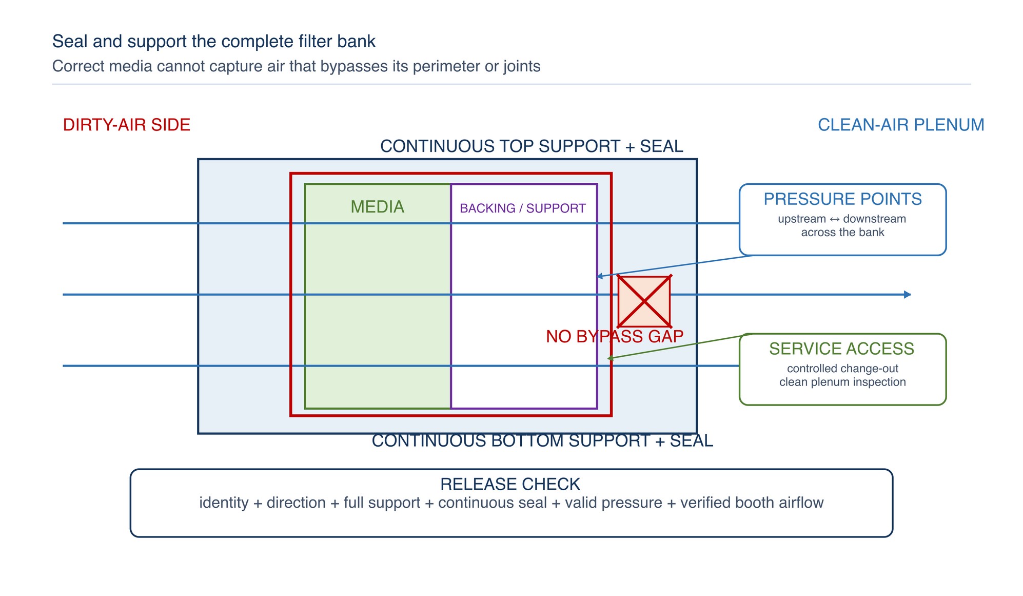
Before spraying:
- Confirm the filter identity and airflow arrow or declared spray side.
- Isolate and secure the booth according to the site procedure before entering the filter area.
- Inspect the frame, clips, grids, channels and seals; remove old residue by an approved non-sparking method.
- Cut or expand the media without damaging its layers, backing or designed pleat geometry.
- Install from one edge in a controlled sequence so every joint and perimeter remains closed.
- Support rolls and pads against sag, flutter or collapse without crushing the media depth.
- Check the upstream face for reverse installation, gaps, folds, tears or exposed frame openings.
- Check the downstream side for bypass paths and loose media before restoring ventilation.
- Verify gauge condition, booth airflow and containment before production release.
For Andreae-type accordion media, the manufacturer identifies correct expansion, white or declared spray-side orientation, secured first and last pleats and continuous top and bottom support as important installation conditions. Use the current instructions for the selected grade. [S186; S187]
Monitor loading by pressure, airflow and pattern
No single observation proves filter condition. A dark or heavily coloured face may still have usable internal capacity; a clean-looking face may conceal deep loading, blocked pockets or a bypass path. Differential pressure shows resistance across the bank, but it does not directly prove airflow or capture.
| Observation | What it may mean | Confirm with | Response |
|---|---|---|---|
| Pressure rises gradually and loading is even | Normal accumulation through the bank | Airflow distribution, fan state and downstream cleanliness | Continue within the established operating method |
| Pressure rises rapidly after a process change | Coating/application change and media | Finer mist, tackier coating, face-loading pattern | Correct the process cause and reassess media construction |
| Pressure remains unusually low | Torn media, reverse installation, gap, gauge fault or low system flow | and airflow measurement | Stop and restore the sealed bank and valid measurement |
| One zone loads much faster | Uneven airflow, gun aimed at the filter, part shielding or local damage | Booth traverse, spray path and frame condition | Correct distribution or work method before replacing the bank |
| Airflow falls as pressure rises | Fan cannot maintain duty | Fan speed, drive, damper and system pressure profile | Replace the loaded media and correct system restrictions |
| Penetration, bypass, failed joint or unsuitable final stage | Perimeter, media integrity and coating droplet character | Stop spraying; repair the bank and select the appropriate stages | |
| Paint runs from the face | Excess wet load, unsuitable media, low airflow or local overspray concentration | Spray rate, transfer efficiency, airflow and filter orientation | Control the application and change to suitable capacity |
Establish the clean-bank baseline after a correct installation. Trend pressure, airflow condition, fan state and loading pattern under comparable production conditions. The replacement point is the earliest applicable limit from the booth operating method, filter instructions, airflow verification, pressure trend, physical condition, fire control or downstream protection requirement.
Control spark, fire and self-heating hazards
Used overspray filters contain coating residue, not merely paper or fibre. The fire behaviour of the loaded filter depends on the coating ingredients, curing reaction, solvent content, deposited mass, airflow, heat sources and the filter construction. OSHA's spray-finishing rule provides transferable safety principles: control combustible deposits, keep mechanical ventilation operating during spraying and clearance, prevent ignition sources, protect dry-filter areas with the required fire-protection system, remove discarded media to a safe controlled location, and do not alternate filters between coating materials where the combination can promote spontaneous ignition. The applicable Malaysian requirements and the authority having jurisdiction govern the installation. [S175; S185]
Apply these practical controls:
- keep grinding, welding, hot work, smoking, unapproved electrical equipment and other ignition sources out of the spray and filter areas;
- maintain bonding, grounding, fan clearances, interlocks and fire-protection equipment as designed;
- do not use a filter with a coating known to self-heat or react unless the complete system is specifically approved for that duty;
- segregate residues from incompatible coating systems, oxidisers, organic peroxides or reactive two-component materials;
- do not stack warm, wet or actively curing filters in an enclosed combustible pile;
- keep upstream and downstream filter spaces accessible and free from loose deposits;
- use non-sparking cleaning tools and the approved residue-removal method; and
- stop spraying if containment, ventilation, an interlock, a fire-control system or the filter bank is not in serviceable condition.
“Flame-retardant”, “self-extinguishing” or a filter classification applies only under the stated test and product condition. It is not a guarantee that paint-loaded media cannot burn. Refer to the product label, Technical Data Sheet, or MKTECH representative.
Change filters without spreading contamination
Plan change-out for the complete bank or controlled zone so clean and loaded media are not mixed. Keep ventilation and isolation states under the booth procedure, and allow the required post-spray clearance before entry.
- Stop spraying and complete the specified ventilation run-on and isolation sequence.
- Confirm the coating identity, required PPE, handling controls and waste container.
- Protect the clean side and prevent dry deposits from being shaken into the booth or plenum.
- Remove media in manageable sections without cutting through heavily loaded pockets where avoidable.
- Place used filters directly into the compatible, labelled container; do not leave them beside the booth.
- Clean the frame and accessible deposits using the approved method without compressed-air blow-off.
- Inspect support, seals, gauge connections, fire-protection components and the downstream plenum.
- Install the replacement bank, verify direction and sealing, then establish the operating condition before spraying.
Do not wash, burn, compact or solvent-clean used filters unless the waste and fire-management system specifically permits that method.
Classify and dispose of used media correctly
The disposal route follows the captured coating residue and process, not the appearance of the clean filter. In Malaysia, the waste generator is responsible for classifying the waste from its source and materials. DOE lists contaminated paper or filters and paint-related sludge within the scheduled-waste framework where the relevant criteria apply; scheduled waste must be managed through the prescribed system and licensed facilities. [S188; S189]
Use the following sequence:
| Step | Practical action | Control point |
|---|---|---|
| Identify | Link the used filter to the coating, hardener, thinner, cleaning agent and process batch | Use current SDS and process information |
| Classify | Determine the applicable Malaysian waste classification | Waste generator applies DOE requirements; do not classify by carrier material alone |
| Segregate | Keep incompatible residues and separately classified streams apart | Prevent reaction, heat generation, fire or cross-contamination |
| Contain | Use a compatible, closed and labelled container in the designated area | Control leaks, vapour, ignition and unauthorised access |
| Record | Maintain the required inventory, date, quantity and movement information | Ensure traceability from booth to authorised destination |
| Transfer | Use the approved transporter and receiving facility where required | Verify licence and consignment controls before release |
Do not assume that a paper or synthetic filter can enter general waste, landfill or incineration because the clean media may be combustible or marketed as disposable. The loaded filter must follow the classification and authorised route for its residue.
Troubleshoot overspray-filter performance
| Symptom | Likely causes | Checks | Corrective direction |
|---|---|---|---|
| Filter blocks too quickly | Media too fine for first-stage load, tacky coating, low transfer efficiency, high spray rate or insufficient area | Coating change, gun setup, loading distribution and clean baseline | Correct application and evaluate a higher-capacity or staged arrangement |
| Paint passes downstream | Media too open, damaged backing, bypass, reverse installation or fine mist character | Full perimeter, joints, downstream pattern and droplet character | Restore the bank and add the appropriate declared final stage |
| Paper filter sags or loses shape | Excess moisture, incorrect expansion, weak support or incompatible coating | Humidity, water-reduced process, clips and frame | Use the declared moisture-compatible construction and correct support |
| Fibrous pad collapses | Wrong airflow direction, compressed loft, inadequate grid or excessive resistance | Backing direction, support and pressure | Replace without compression and restore the support arrangement |
| Paint runs or drips from face | Excess wet loading, low airflow, poor atomisation or unsuitable storage volume | Spray path, transfer efficiency, airflow and face angle | Stop, clean safely and select higher wet-load capacity |
| One row remains clean | Bypass elsewhere, blocked upstream distribution or uneven exhaust | Airflow traverse, frame gaps and plenum condition | Restore balanced flow and continuous sealing |
| Pressure high immediately after change | Wrong grade, over-compressed media, excessive stages or obstructed frame | Identity, orientation, stage count and fan system | Install the correct construction and verify fan duty |
| Pressure low but capture poor | Torn media, open seam, gauge fault or insufficient airflow | Gauge zero, physical bank and measured flow | Repair measurement and filter integrity before spraying |
| Smouldering odour or heat | Reactive residue, hidden ignition, self-heating or hot deposit | Emergency response, coating chemistry and thermal condition | Stop work, isolate safely and activate the site emergency plan |
| Filter fibres or paper fragments appear downstream | Damaged media, poor support, unsuitable cleaning or excessive vibration | Backing, grid, fan vibration and handling | Replace damaged media and correct the mechanical cause |
Practical selection and release sequence
Use this sequence for a new filter, coating change or persistent performance problem:
- Define the coating family, spray method, normal output and overspray behaviour.
- Confirm the booth airflow route, filter-face area, frame depth, support and fan duty.
- Choose the required capture mechanism: inertial paper, expanded paper, fibrous depth media or a combination.
- Decide whether a high-capacity first stage and finer downstream stage are needed.
- Check moisture, chemical, mechanical and fire compatibility for the complete media construction.
- Confirm the intended direction, installation method, clean resistance and replacement criteria.
- Establish the waste classification, segregation and container before the first loaded filter is removed.
- Install and seal the complete bank; record the filter identity and date.
- Verify airflow, pressure, containment and downstream cleanliness under the normal production arrangement.
- Trend performance and revise the selection only through the controlled booth-change process.
Concise safety reminders
- Never spray with missing, torn, reversed, collapsed or bypassed overspray filters.
- Keep the filter bank, plenum, duct and fan accessible and free from unsafe residue accumulation.
- Treat every used filter according to the captured coating, not the clean carrier material.
- Keep incompatible coating residues in separate controlled waste streams.
- Do not bypass filters or increase fan limits to hide a loaded or unsuitable bank.
- Keep ignition sources and hot work outside the controlled spray and filter areas.
- Maintain ventilation, interlocks, grounding and fire protection in their designed state.
- Use the coating SDS, current booth procedure and specified PPE during inspection and change-out.
- Stop work for smoke, heat, smouldering odour, sudden pressure change, overspray escape or downstream breakthrough.
Filter Selection
The Filter Selection matrix appears on the following page of the printed handbook (page 276), outside this chapter extract.