
Production engineers, supervisors, operators, painters, QA/QC personnel, maintenance teams, safety and environmental personnel, procurement staff and technical sales personnel
Practical guidance for understanding and controlling airflow direction, air velocity, pressure drop, overspray capture, intake and exhaust filtration, booth balance, fan load, coating quality, worker exposure and environmental discharge in industrial paint booths.
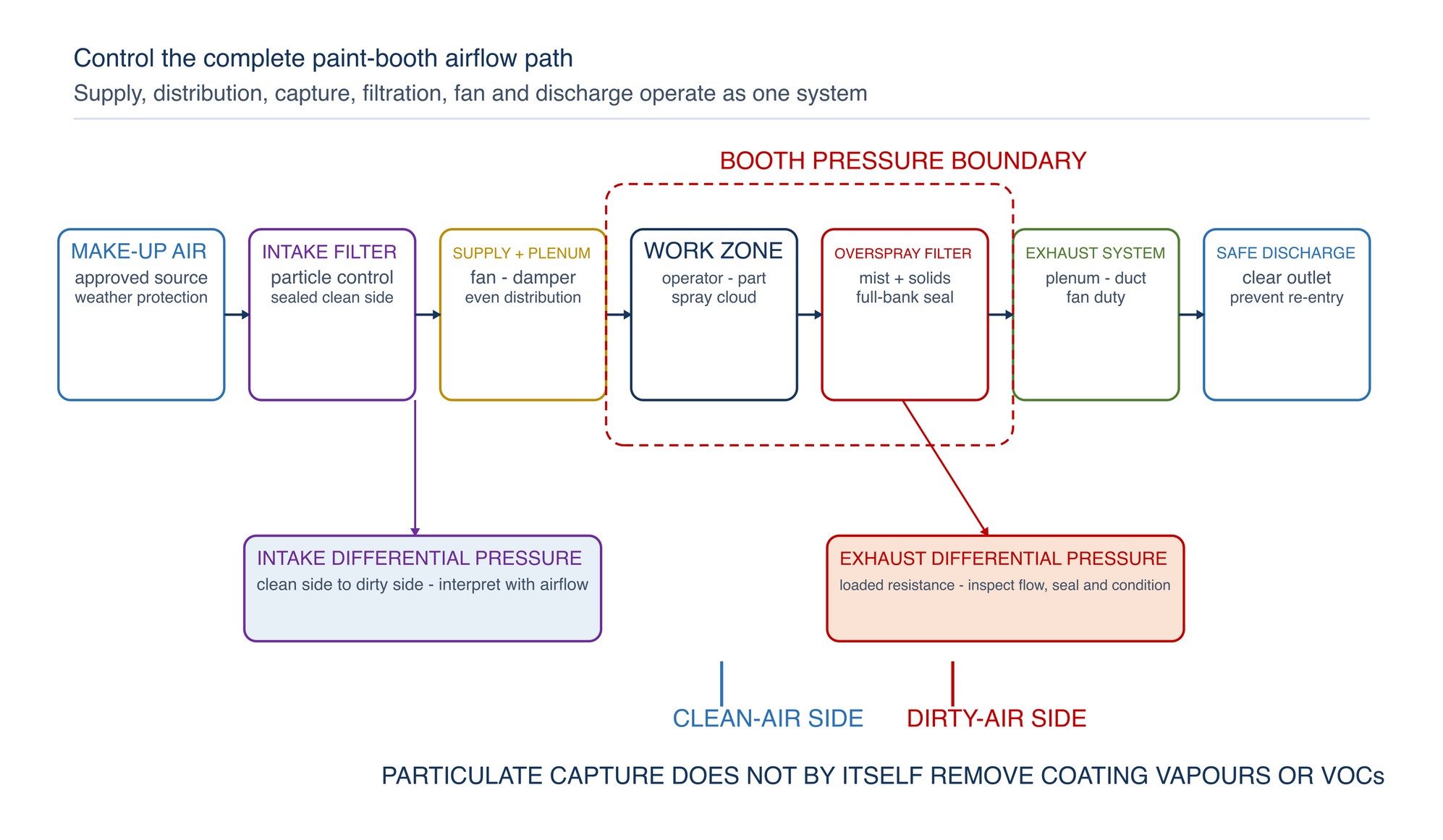
A paint booth works as one connected air-handling system. Control the path from clean make-up air to safe discharge, and verify airflow, pressure and filter condition together. A filter cannot compensate for poor distribution, leakage, obstruction or an unsuitable fan duty point.
Spray atomisation creates a fast-moving cloud of coating droplets and vapour. The booth must contain that cloud, carry overspray away from the operator and workpiece, remove captured particulate before discharge, and maintain a clean, stable environment around the wet coating. These functions depend on the combined performance of the supply opening, intake filters, plenum, booth enclosure, exhaust filters, ductwork, fan and discharge point. [S171; S172; S174; S175]
This chapter explains the fundamentals that apply across dry-filter liquid-coating booths. Water-wash booths, powder systems, recirculation systems and specialised solvent controls require their own engineered arrangements and operating procedures.
Use the booth only for the coating processes, work sizes and operating modes covered by its current instructions and risk assessment. Confirm mechanical ventilation, airflow indication, interlocks and alarms before spraying. Keep ignition sources, unsuitable electrical equipment, hot work and incompatible materials out of the spray area. Never operate with missing, damaged, bypassed or improvised filter media. Isolate energy and follow the filter-change procedure before opening plenums, reaching into fans or servicing the air path. Follow the current authority, fire code, environmental approval, booth manual and site procedures. NFPA 33 is a recognised fire-safety reference where adopted by the authority having jurisdiction. [S173; S185]
Chapter objectives
After this chapter, the reader should be able to:
- trace the complete airflow path through a paint booth;
- distinguish crossdraft, semi-downdraft, side-downdraft and downdraft arrangements;
- explain why average velocity, distribution and direction must be considered together;
- interpret differential pressure without mistaking it for a direct airflow reading;
- separate the functions of intake filters and exhaust overspray arrestors;
- recognise how filter loading changes airflow, fan duty and coating quality;
- identify pressure-balance symptoms at doors, gaps and filter frames;
- apply practical checks for worker exposure and post-spray clearance;
- separate particulate capture from vapour and VOC control; and
- troubleshoot airflow and filtration as one connected system.
Treat the booth as a complete control system
The booth enclosure is the capture zone, but the enclosure alone does not create control. Air must enter through the intended clean path, travel through the work zone without harmful recirculation, pass through the correct exhaust treatment and discharge to a safe location. DOSH Malaysia describes an enclosure hood such as a spray-painting booth as a local exhaust ventilation control whose effectiveness depends on adequate, uniformly distributed flow and the performance of the complete system. [S171; S172]
| System element | Primary function | Condition to verify | Typical consequence if uncontrolled |
|---|---|---|---|
| Make-up-air source | Replaces extracted air | Clean location, adequate supply and no exhaust re-entry | Starved booth, unwanted inward drafts or contaminated intake |
| Intake filter and plenum | Cleans and distributes supply air | Correct media, orientation, sealing and even loading | Dirt on wet coating or non-uniform airflow |
| Booth enclosure and openings | Define the pressure boundary and airflow route | Doors, panels, lights, joints and intentional openings intact | Bypass air, leakage and unstable capture |
| Work zone | Carries spray cloud away from people and accepted surfaces | Part and operator positioned for the designed flow | Recirculation, overspray escape and coating defects |
| Overspray arrestor | Captures coating mist and solids before the exhaust path | Correct media, full-bank sealing and controlled loading | Breakthrough, duct deposits and emissions |
| Exhaust plenum and duct | Collect and convey contaminated air | Cleanable, sealed and free from obstruction | Uneven suction, residue accumulation and leakage |
| Fan and drive | Overcome system resistance and deliver the duty airflow | Rotation, condition, control response and operating point | Low flow, instability, vibration or excess energy use |
| Discharge | Releases treated exhaust at the intended location | Clear outlet, suitable direction and separation from air intakes | Re-entry, nuisance deposition or uncontrolled exposure |
Select an airflow arrangement around the work
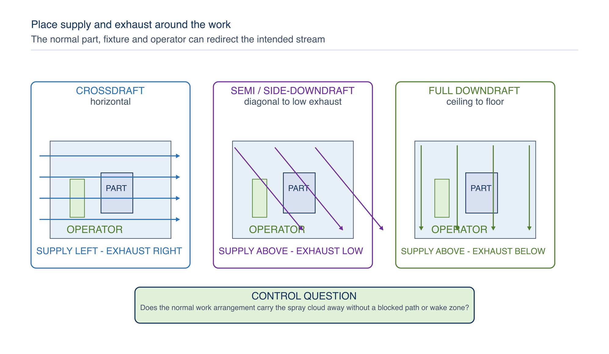
Airflow arrangement describes the main direction between the clean-air supply and the exhaust. Crossdraft booths move air broadly from one end to the other. Semi-downdraft systems introduce air overhead and move it diagonally to a low exhaust. Side-downdraft systems supply from above and extract low at the sides. Full downdraft systems move air from a ceiling plenum towards a floor or low-level exhaust. These are established families, but the best choice depends on work geometry, operator movement, process, building layout, contamination sensitivity and the engineered ventilation duty. [S184]
| Arrangement | Main flow route | Practical strengths | Control considerations |
|---|---|---|---|
| Crossdraft | Horizontal, supply end to exhaust end | Simple path, clear upstream and downstream relationship, adaptable to long workpieces | Part and operator can obstruct the path; floor and door drafts can disturb distribution |
| Semi-downdraft | Overhead front supply to low rear exhaust | Directs air away from the clean entry zone without a full floor pit | Diagonal flow can create shadow zones behind large parts |
| Side-downdraft | Ceiling supply to low side exhausts | Removes overspray towards both sides and can avoid a central pit | Side banks must remain balanced; large work can shield one side |
| Full downdraft | Ceiling supply vertically to floor or low exhaust | Separates clean overhead supply from low exhaust and suits controlled production layouts | Floor grilles, pits and large horizontal surfaces can change local flow |
The intended arrangement is only the starting geometry. A large product, fixture, platform, open door or operator can split the stream and create wake zones. Evaluate airflow with the normal part, support and work position in place, while preserving a safe test method.
Control direction before increasing velocity
Direction determines where overspray and vapour travel. The spray gun ejects coating at much higher local speed than the general booth airflow, so extraction cannot simply pull every droplet backwards at the gun. The control objective is to contain and sweep the dispersed cloud after atomisation, keeping the operator out of the downstream plume where the designed process permits. [S172; S177]
Arrange the part and spraying sequence so the operator does not repeatedly spray into their own breathing zone or block the path to the exhaust. Use turntables, fixtures or planned access where appropriate so the work can be presented to the airflow rather than forcing the painter to stand downstream. Check that large surfaces do not form a wall across the booth or create a protected pocket behind the component.
Crosscurrents from doors, fans, compressed-air blow-off, nearby extraction, vehicle movement or building pressure can overcome the intended stream at an opening. Increasing fan speed may not correct a badly directed crosscurrent and can create more turbulence. First remove the disturbance, restore the intended openings and check distribution.
Measure air velocity as a distribution
Air velocity is the local speed of air at a stated plane and under stated operating conditions. Volume flow is related to average velocity and open area:
Volume flow = average velocity x effective open area
This relationship is useful only when the measurement plane and effective area are defined. A single centre reading cannot represent a large booth face, ceiling or filter bank. Use a planned traverse or the booth's specified verification method, compare readings across the intended plane, and record the operating condition of doors, fans, dampers, filters and production equipment.
Uniformity matters because two booths can have the same calculated average while one has strong jets and weak pockets. High local velocity can disturb the spray pattern, increase turbulence, dry the coating unevenly or draw contamination from gaps. Low local velocity can allow overspray to linger, escape or settle on the work. DOSH guidance therefore links effective enclosure control with both sufficient velocity and uniform distribution across the capture face. [S171]
Use smoke visualisation or another approved qualitative method only under safe non-spraying conditions and with materials suitable for the booth. Smoke can reveal reverse flow, dead zones, leakage and slow clearance, but it does not replace quantitative measurement or exposure assessment.
Read pressure drop correctly
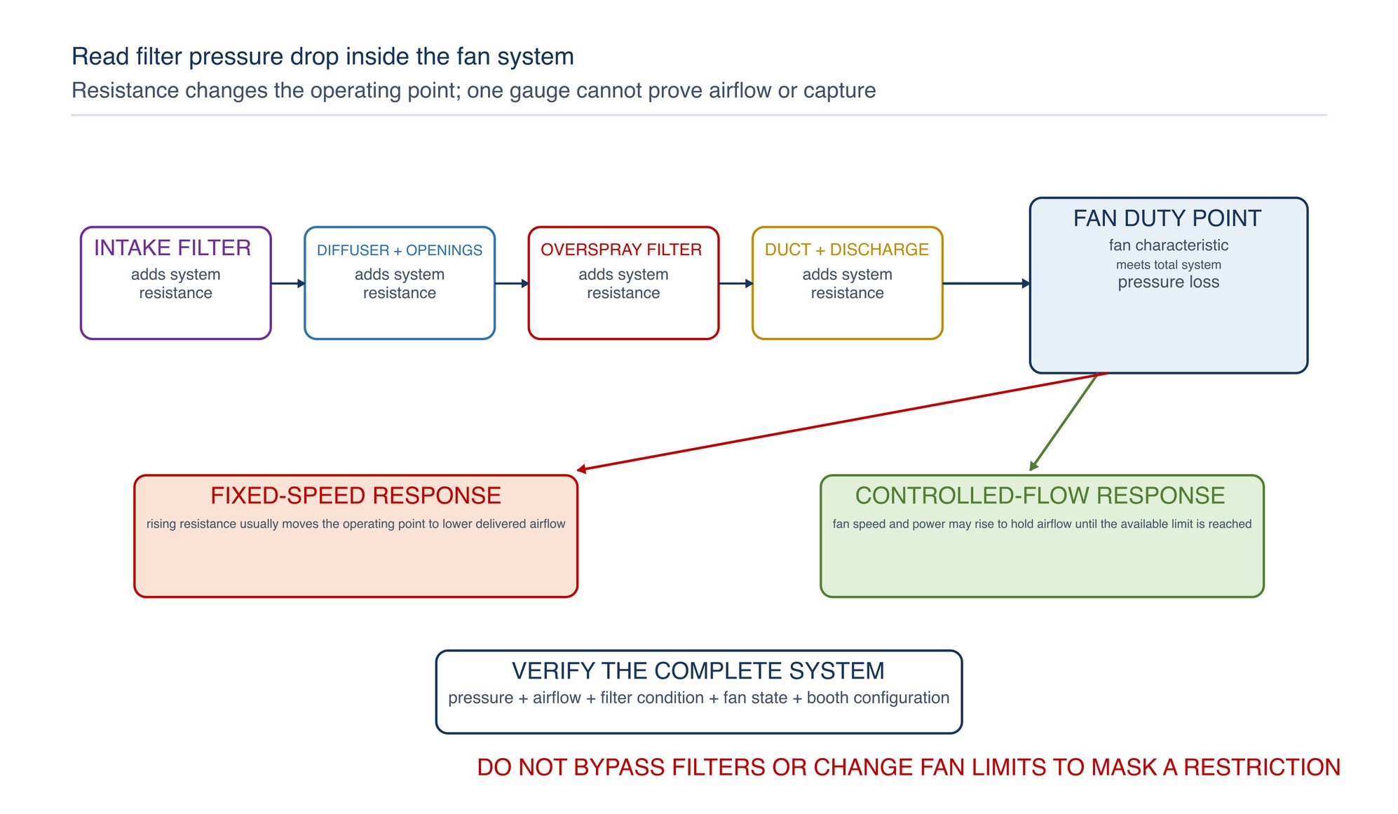
Differential pressure is the pressure difference across a filter bank or another system section. It indicates resistance to airflow. Clean media has an initial resistance at a stated flow. As dust or overspray accumulates, resistance normally rises. The fan and controls then determine whether airflow falls, fan speed rises, power changes or the system reaches an alarm or control limit. [S174; S179; S180]
Pressure drop is not a direct measure of capture efficiency, remaining filter life or booth velocity. A low reading can mean a clean filter, low airflow, a missing panel, a split medium, an open bypass or incorrectly located pressure taps. A high reading can indicate loading, wet or collapsed media, excessive flow, a blocked downstream path or an unsuitable replacement. Always interpret pressure with airflow, physical condition and system configuration.
| Pressure indication | Airflow observation | Likely interpretation | First check |
|---|---|---|---|
| Rising pressure drop | Airflow falling | Loading is increasing total resistance and the fan is not maintaining flow | Filter bank, fan duty and downstream obstruction |
| Rising pressure drop | Airflow stable | Controlled fan may be increasing speed or power to maintain duty | Fan control, motor load and remaining pressure capacity |
| Low pressure drop | Airflow low | Flow may be too low to develop the expected filter resistance | Fan, damper, drive, duct and measurement point |
| Low pressure drop | Dust or overspray downstream | Media, seal or frame may be bypassed or damaged | Full perimeter, joints, orientation and bank completeness |
| Sudden pressure change | Unstable or noisy flow | Filter movement, collapse, damper change, fan fault or instrument problem | Stop and inspect the complete air path |
| Uneven bank readings | Uneven face velocity differs across the bank | Plenum distribution, local loading, blockage or sealing | Traverse the bank and inspect upstream distribution |
Use intake filtration to protect the process
Intake filtration reduces dust, fibres, insects and other particles entering with make-up air. Its main production purpose is a cleaner wet-film environment and more uniform air distribution. A staged intake may include coarse protection followed by a finer final supply filter, but the correct arrangement depends on the air source, finish requirement, booth design and fan capacity.
Filter efficiency cannot be selected independently of resistance. A finer or deeper filter may improve particle control but can also change pressure drop and fan duty. General-ventilation filters may be classified and tested under the ISO 16890 series, including airflow resistance and dust-loading behaviour, but laboratory classification does not by itself predict service life in a particular paint booth. [S181; S182; S183]
Install media in the stated airflow direction and provide full support. Seal the perimeter, panel joints and access doors so air cannot choose a lower-resistance route around the filter. Keep the clean side protected during replacement; contamination released downstream of the final intake stage can deposit directly on wet work.
Do not assume that a visually clean filter has low resistance or that a dark filter has failed. Use the specified differential-pressure and airflow checks with inspection. For exact media class, dimensions, orientation, initial and final resistance, rated airflow, compatibility and replacement limit, Refer to the product label, Technical Data Sheet, or MKTECH representative.
Capture overspray before the exhaust path
The exhaust filter or overspray arrestor captures coating droplets and solids carried from the work zone. It protects the downstream plenum, duct, fan and discharge path from excessive deposits and reduces particulate emissions. It is not the same product function as an intake filter, and the two should not be interchanged merely because they fit the same frame.
Overspray loading depends on coating solids, spray rate, transfer efficiency, part geometry, gun technique, production time and airflow distribution. A filter that performs well with one coating process may load rapidly, drain, soften, shed, react or permit breakthrough with another. Chapter 33 explains construction families; Chapter 34 develops the selection route.
Inspect the complete bank for uniform loading. A clean corner beside a heavily loaded centre can indicate poor distribution, a blocked part position or air bypass. Darkening or deposit alone is not a reliable end-of-life rule unless the filter instructions use it. Track differential pressure, airflow, loading pattern, downstream cleanliness and production condition together.
Never cut, compress, stretch, reverse or stack media unless the product and booth instructions permit that arrangement. Uncontrolled modification changes flow passages, support, resistance, holding behaviour and fire characteristics.
Control booth balance and leakage
Booth balance is the relationship between supplied and exhausted air, including every intentional opening and leakage path. The designed pressure condition may be negative, neutral or positive relative to the surrounding room depending on the booth type and process. The correct target is the engineered operating condition, not a universal pressure sign.
Too much exhaust relative to supply can pull dirty shop air through door gaps, panel joints and cable openings. This may increase dust defects, make doors difficult to operate and disturb temperature control. Too much supply relative to exhaust can drive vapour, odour or overspray out through openings. A nominal pressure indication can still hide local leakage if seals or distribution are poor.
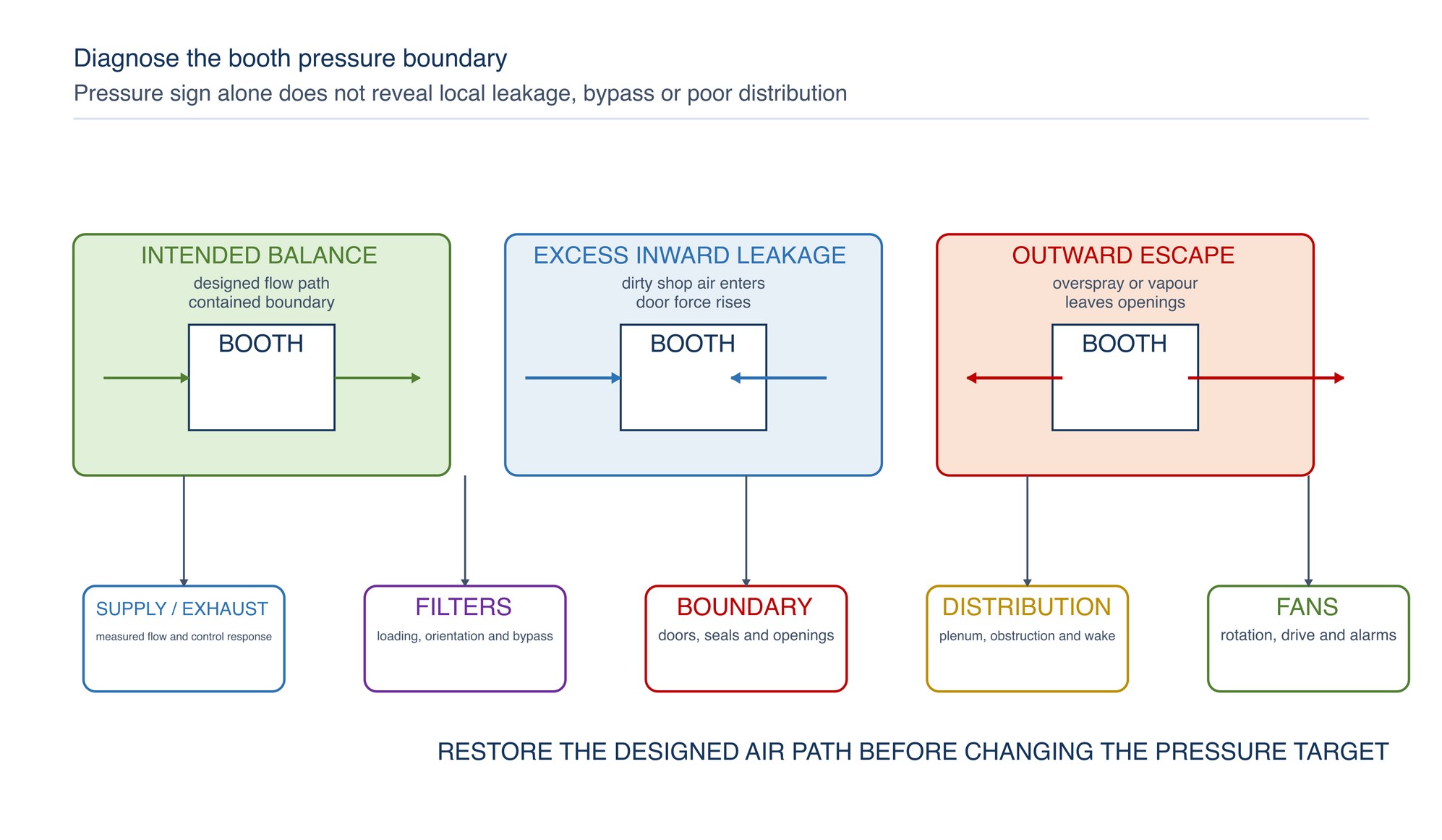
| Observed condition | Pressure-boundary meaning | Common contributors | Controlled response |
|---|---|---|---|
| Excess inward leakage — Dust drawn through gaps | Poor intake sealing | Supply restriction, high exhaust, damaged panels or open penetrations | Restore supply path and seals; verify complete balance |
| Overspray or odour escapes at doors | Outward leakage, poor capture or disturbed direction | Excess supply, low exhaust, crossdraft, blocked bank or open door | Stop spraying, contain the area and verify exhaust and distribution |
| Door force changes during a shift | Balance is changing as resistance or fan control changes | Filter loading, damper movement, fan fault or building pressure | Check pressure, airflow, fans and adjacent systems |
| One filter bank loads much faster | Air distribution is not balanced across the exhaust face | Plenum restriction, work obstruction, leakage or uneven media | Inspect face velocity and the upstream flow path |
| Booth pressure appears stable but finish worsens | Average balance can hide local recirculation or dirty supply | Part wake, blocked diffuser, intake bypass or local turbulence | Traverse airflow and inspect the normal production arrangement |
Understand fan load and the operating point
A fan delivers airflow at the pressure required by the system. The operating or duty point is where the fan characteristic and system resistance meet. Filters, plenums, diffusers, dampers, ducts, bends, stacks and deposits all contribute resistance. AMCA and US Department of Energy guidance treat fan performance as a system interaction rather than an isolated nameplate value. [S179; S180]
With a fixed-speed fan, rising resistance commonly reduces delivered airflow. With a variable-speed or pressure-controlled fan, the controller may increase speed and power to maintain a set condition. The booth can therefore appear to hold airflow while the motor approaches its limit or energy use rises. A control signal is not proof that the physical system is healthy.
Trend the indicators that matter to the installed design: filter-bank pressure drop, booth pressure, representative airflow, fan speed, motor current or power, damper position and alarms. Investigate a change in relationship, such as more fan effort for the same airflow, before the system loses control.
Do not compensate for a restricted filter by bypassing media, opening uncontrolled gaps or exceeding equipment limits. Restore the designed air path and use a compatible replacement.
Link airflow to coating quality
Coating quality depends on material preparation, atomisation, application technique, temperature, humidity, flash-off and curing as well as booth airflow. The airflow system cannot correct an unsuitable coating process, but it can introduce or amplify visible defects.
| Finish symptom | Possible airflow or filtration contribution | Confirming check | Corrective direction |
|---|---|---|---|
| Dust nibs or fibres | Intake bypass, dirty clean side, shedding media or leakage from clean shop | Inspect particle pattern, intake seals and clean-side handling | Restore intake integrity and clean using an approved method |
| Dry spray or rough texture | Excess local velocity, turbulence, long spray distance or unsuitable application condition | Compare defect with airflow map and gun path | Correct distribution and application variables together |
| Uneven gloss or colour | Non-uniform flow, temperature or flash-off across the part | Compare zones with supply pattern and part shadowing | Stabilise distribution and environmental condition |
| Overspray settling on wet film | Weak capture, recirculation or workpiece wake | Use safe airflow visualisation and inspect exhaust-face uniformity | Reposition work or restore the designed route |
| Repeating dirt from one area | Damaged ceiling media, frame bypass or contaminated plenum | Trace the defect location to the upstream zone | Repair seal or media and clean the affected clean side |
| Edge or side remains hazy | Side bank imbalance or spray plume crossing accepted work | Compare both exhaust banks and operator route | Restore bank balance and revise work presentation |
Release coating appearance only after the air system is stable under the normal production arrangement. An empty-booth test may not show wake zones created by the actual part, fixture or operator.
Protect workers during spraying and clearance
Ventilation is an engineering control, but it does not automatically reduce every hazardous substance below the applicable exposure requirement. Coating droplets, solvents, isocyanates, metals and other ingredients require assessment from the actual Safety Data Sheet, process and workplace exposure conditions. Fire-safe ventilation and flammability control do not by themselves prove toxic-exposure control. [S153; S160; S175; S177]
Keep the operator on the clean-air side of the spray cloud where the booth design and task allow. Avoid directing the gun towards another person, an exit or an uncontrolled opening. Maintain mechanical ventilation during spraying and for the required period afterwards. Respiratory, skin, eye and body protection must be selected through the current chemical-risk assessment and site programme.
Post-spray clearance is the time needed for airborne contamination to be removed after spraying stops. HSE guidance recommends establishing clearance under worst-case service conditions, including near the filter-change condition, and clearly communicating when entry or removal of respiratory protection is permitted. [S176; S177]
Do not use odour or visible mist alone as the clearance indicator. Some hazardous vapours are poorly detected by smell, and fine aerosol may remain after the obvious cloud disappears.
Separate particulate capture from vapour control
Dry overspray arrestors primarily capture coating droplets and solids. Ordinary particulate filters generally do not remove solvent vapours or VOCs. EPA guidance makes this distinction explicit: a booth can capture overspray particulate while vapour remains in the exhaust stream. [S178]
VOC, hazardous-air-pollutant and odour control may require coating reformulation, improved transfer efficiency, enclosure, dedicated adsorption, thermal or catalytic treatment, wet collection, or another engineered process. Selection depends on the actual coating chemistry, emission rate, regulatory requirement and control-system design.
Discharge treated air to the approved location away from doors, occupied zones and air intakes so contaminants are not drawn back into the building. Malaysia's Environmental Quality (Clean Air) Regulations 2014 establish the national environmental framework for air-pollution-control systems and emissions. Site design, notification, monitoring and limits must follow the current requirements applicable to the installation. [S173]
Captured filters and residues remain process waste. Store and dispose of them according to coating chemistry, fire risk, Safety Data Sheet information and Malaysian waste requirements. Do not treat a dry filter as harmless because the carrier frame is paper or synthetic fibre.
Verify the booth before production
Use a repeatable release check at start-up, after maintenance, after filter change and whenever airflow, coating quality, odour, fan load or booth pressure changes.
| Verification point | What to observe or measure | Accept when | Escalate when |
|---|---|---|---|
| Air path | Supply opening to discharge, including doors and dampers | Intended path is open, complete and unobstructed | Temporary covers, closed dampers, deposits or blocked grilles are found |
| Filter installation | Identity, direction, support, joints and perimeter | Correct media is fully seated and sealed | Gaps, reverse installation, collapse, damage or improvised packing are present |
| Differential pressure | Each controlled filter bank and relevant system section | Reading is stable within the installed operating method | Sudden, unexplained, high, low or unequal readings occur |
| Airflow distribution | Specified plane and representative traverse | Direction, average and distribution meet the booth method | Reverse flow, dead zones, strong jets or low capture are found |
| Booth balance | Door behaviour, boundary pressure and leakage | Pressure condition matches the engineered state | Overspray escapes or dirty air is drawn through uncontrolled gaps |
| Fan and drive | Rotation, noise, vibration, speed, load and alarms | Stable operation supports the required airflow | Fan effort rises, flow falls, vibration develops or an alarm is active |
| Cleanliness | Intake clean side, booth, exhaust face, plenum and discharge path | No loose debris, residue release or downstream breakthrough | Dirt can enter the wet-film zone or deposits threaten the exhaust |
| Clearance control | Ventilation run-on and communicated clearance status | Entry and protective-equipment rules are clear and functional | Timing, indicator or safe exit arrangement is uncertain |
Record the booth identity, coating process, filter type, installed condition, pressure readings, airflow result, fan state, inspector and action taken. Trends are often more useful than isolated readings because they show how resistance and fan response change across filter life.
Troubleshoot the complete air path
| Symptom | Likely system causes | Checks | Corrective direction |
|---|---|---|---|
| Overspray escapes from the opening | Low exhaust, excess supply, crossdraft, blocked arrestor or work obstruction | Direction at opening, filter pressure, fan state and normal part position | Stop spraying and restore containment before resuming |
| Airflow is reduced | Loaded filters, fan or drive fault, closed damper, blocked duct or discharge | Pressure profile, fan rotation, speed and system inspection | Correct the resistance or fan fault; do not bypass filters |
| Dust appears on painted parts | Intake bypass, dirty plenum, shedding media or excessive inward leakage | Clean side, seals, upstream air source and booth balance | Restore clean-air integrity and approved cleaning |
| Finish becomes uneven | Non-uniform velocity, temperature gradient, workpiece wake or side-bank imbalance | Traverse airflow around the production arrangement | Rebalance distribution and part presentation |
| Filter use rises sharply | More overspray, changed coating, poor transfer, higher spray rate or unsuitable media | Compare production, loading pattern and pressure trend | Correct application cause and confirm compatible media |
| Fan load increases | Rising resistance, fouled duct, control response or mechanical fault | Filter and system pressure, fan speed, motor condition | Restore the system before the operating limit is reached |
| Symptom | Likely system causes | Checks | Corrective direction |
|---|---|---|---|
| Filter bypass is visible | Poor fit, damaged seal, collapsed panel or incorrect support | Inspect full perimeter and downstream deposits | Replace and seal using the approved arrangement |
| Odour remains or returns | Vapour not controlled by particulate media, re-entry or poor clearance | Discharge location, ventilation run-on and coating chemistry | Apply the chemical-risk and environmental control route |
| Pressure drop is normal but capture is poor | Instrument fault, low-flow baseline, local dead zone or opening change | Verify gauge zero, airflow distribution and booth configuration | Correct measurement and restore the design condition |
| One area blocks prematurely | Uneven flow, spray aimed at the bank, part shielding or local media damage | Compare face loading and spray path | Correct distribution or work method before replacing the bank |
Concise safety reminders
- Use the booth only for the coating processes, work sizes and operating modes covered by its current instructions and risk assessment.
- Confirm mechanical ventilation, airflow indication, interlocks and alarms before spraying.
- Keep doors and intentional openings in their stated operating position; do not defeat interlocks or pressure controls.
- Keep ignition sources, unsuitable electrical equipment, hot work and incompatible materials out of the spray area.
- Maintain ventilation during spraying and throughout the established post-spray clearance period. [S175; S176]
- Select respiratory, eye, face, skin and body protection from the coating Safety Data Sheet and current chemical-risk assessment.
- Isolate energy and follow the filter-change procedure before opening plenums, reaching into fans or servicing the air path.
- Treat used filters and deposits as coating-contaminated material; control ignition, exposure, storage and disposal.
- Never operate with missing, damaged, bypassed or improvised filter media.
- Follow the current authority, fire code, environmental approval, booth manual and site procedures. NFPA 33 is a recognised fire-safety reference where adopted by the authority having jurisdiction. [S173; S185]
Practical operating verification sequence
- Confirm the booth, coating, part size and operating mode are authorised for the planned work.
- Inspect the make-up-air intake and discharge location for blockage, contamination or re-entry risk.
- Check intake and exhaust filters for correct identity, orientation, support, sealing and condition.
- Inspect doors, panels, lights, floor grilles, plenums and intentional openings.
- Start the ventilation system and confirm fan rotation, stable running, indicators, interlocks and alarms.
- Record differential pressure across each controlled filter bank.
- Verify airflow direction and distribution using the specified method and normal booth configuration.
- Place the work and fixture so they do not block the designed path or force the operator downstream of the plume.
- Confirm the booth pressure condition contains overspray without drawing dirty air through uncontrolled gaps.
- Check the clean-air side, work zone and exhaust path for loose dust or residue.
- Confirm protective equipment, safe entry, exit and post-spray clearance arrangements.
- Spray only when the system is released and keep ventilation operating throughout the process.
- Watch for changing door force, pressure, airflow, fan sound, visible escape, dust or finish quality during the run.
- Stop if containment, ventilation, filter integrity, interlock or fire-safe operation is uncertain.
- After spraying, maintain ventilation and access controls for the established clearance period.
- Record readings, filter condition, abnormalities, corrective work and release decision.
Paint-Stop and Overspray Filters
The Paint-Stop and Overspray Filters chapter appears on the following pages of the printed handbook, outside this chapter extract.