

Machinists, fabricators, grinding and finishing teams, production operators, inspectors, supervisors, maintenance personnel and technical sales personnel
Practical use of vernier, dial and digital calipers and outside micrometers for common industrial measurements, including instrument selection, pre-use checks, surface preparation, temperature control, alignment, contact force, outside, inside, depth and step measurement, repeat-position checks, result recording and troubleshooting.
Do not spin the thimble rapidly into the work, use the micrometer as a clamp, force the spindle with the frame, or drag precision faces across an abrasive surface.
If the instrument fails a required check, isolate it from acceptance work and follow the authorised verification, adjustment, calibration or repair route. Do not adjust repeatedly until one reading agrees.
A displayed number is useful only when the correct feature has been contacted in the correct location and direction with a suitable instrument, controlled force and a traceable measurement process.
Calipers are versatile, fast and useful for many workshop measurements. Outside micrometers provide more controlled opposed-face measurement when the feature, access and required decision suit them. Neither instrument automatically measures form, location, orientation, surface texture or hidden geometry. Correct technique begins with the drawing requirement and ends with a result that another competent person can understand and reproduce. [S232; S234; S237]
Chapter objectives
After this chapter, the reader should be able to:
- identify the feature, characteristic, location, orientation, unit, tolerance and decision requirement;
- select between a caliper, outside micrometer or a more suitable dedicated method;
- recognise the functional measuring surfaces and controls on common instruments;
- check cleanliness, damage, smooth movement, zero behaviour and a suitable known reference;
- control burrs, coatings, roughness, support, temperature and hand heat;
- read vernier, dial and digital indications without parallax, unit or reference-mode errors;
- measure outside features with the jaws square to the part and the measuring axis;
- measure accessible inside diameters by finding the true diameter in the required plane;
- seat depth and step references fully without bridging chamfers, radii or debris;
- use an outside micrometer with aligned faces and consistent constant-force operation;
- avoid deforming soft, thin, flexible or hot workpieces;
- repeat at meaningful positions to reveal taper, ovality, wear and local variation;
- record the instrument, location, orientation, unit, reference check and result; and
- recognise when uncertainty, access or contact geometry requires a different measurement route.
Begin with the feature and the decision
Read the complete drawing, work instruction or inspection plan before selecting the instrument. Confirm:
- part and feature identity;
- characteristic to be measured;
- location, section and orientation;
- whether the requirement concerns an outside size, inside size, depth, step, thickness, gap or another property;
- unit, nominal value and limits;
- surface condition and manufacturing stage;
- required number and distribution of measurement positions;
- applicable decision rule and reporting precision; and
- instrument or method restrictions.
A two-point size reading does not automatically establish roundness, cylindricity, parallelism, flatness, position or the complete form of a feature. If the requirement is geometrical rather than a simple accessible size, use the measurement process specified for that characteristic. [S236; S237]
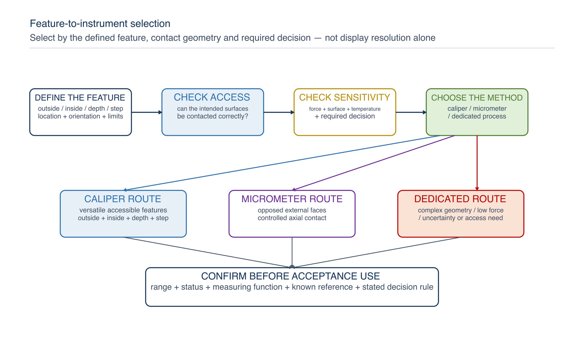
Choose the instrument by contact geometry
Use the simplest instrument that can contact the required feature correctly and support the decision. Do not select by display resolution alone.
| Measurement task | Usually suitable starting point | Key contact requirement | Route elsewhere when |
|---|---|---|---|
| Accessible outside width or diameter | Outside jaws of a suitable caliper | Jaws square to feature with clean face contact | Tolerance, force sensitivity or access requires greater control |
| Opposed external faces or diameter | Outside micrometer | Anvil and spindle aligned with the measuring axis | Contact shape, part form or accessibility is unsuitable |
| Accessible internal diameter | Caliper inside jaws | Correct plane and true-diameter search | Hole is small, deep, short, tapered or accuracy need exceeds the method |
| Depth from a defined reference surface | Caliper depth rod or a dedicated depth instrument | Reference surface fully seated and rod aligned | Base is narrow, curved, obstructed or unstable |
| Step or shoulder difference | Caliper step faces where designed for the task | Both reference faces seat on the intended surfaces | Chamfer, radius or access prevents representative contact |
| Thin, soft or compliant material | Task-specific low-force or non-contact method where needed | Controlled force without deformation | Ordinary jaws or micrometer force changes the measurand |
| Groove, wall, blade, thread or complex form | Dedicated instrument and contacts defined feature | Contact geometry matches the specified surface | General-purpose faces cannot reach the specified surface |
The exact range, resolution, maximum permissible error, measuring force, environmental protection and approved accessories are instrument specific. Refer to the product label, Technical Data Sheet, or MKTECH representative. [S232; S234; S255]
Know which surfaces perform the measurement
On a typical caliper, distinguish:
- beam and main scale;
- slider, gib and thumb control;
- outside jaws and outside measuring faces;
- inside jaws and inside measuring faces;
- depth rod or blade and depth reference surface;
- step measuring faces where provided;
- lock and fine-control features where provided; and
- vernier, dial or electronic indication and unit/reference controls.
On a typical outside micrometer, distinguish:
- rigid frame and insulating grip area where provided;
- fixed anvil and moving spindle measuring faces;
- sleeve or barrel, thimble and analogue graduations;
- electronic display and controls where provided;
- spindle lock;
- ratchet stop, friction thimble or other constant-force device; and
- setting standard supplied for ranges that do not close to zero.
Do not use non-measuring surfaces as datums. Jaw backs, beam edges, frame surfaces and protective tips may not represent the intended measuring geometry.
| Instrument or indication | Confirm before use | Common error to prevent |
|---|---|---|
| Vernier caliper | Main and vernier scales are legible; zero lines and jaw condition are checked | Choosing the wrong coincident line or viewing at an angle |
| Dial caliper | Pointer returns consistently; rack and pinion travel smoothly; revolution is understood | Combining the dial value with the wrong beam interval |
| Digital caliper | Unit, sign, zero/reference mode and battery condition are confirmed | Treating a relative reference as an absolute zero |
| Analogue micrometer | Sleeve, thimble and any vernier graduation are read in the correct order | Missing a sleeve graduation or reading with parallax |
| Digital micrometer | Unit, origin/preset state, display stability and constant-force action are confirmed | Trusting the display while alignment or force remains uncontrolled |
Perform a disciplined pre-use check
Before measuring:
- confirm the instrument identity, range, status and intended unit;
- inspect jaws, anvil, spindle, depth surfaces and reference faces for damage, wear, corrosion or embedded debris;
- wipe measuring faces with a clean compatible material;
- move the slider or spindle through the required region and feel for sticking, looseness, shock or abnormal drag;
- check analogue scales for legibility and dial pointers for stable return;
- check electronic display, battery indication, unit and reference mode;
- close or set the instrument gently using its normal measuring action;
- perform the required zero check; and
- check a suitable known reference when the measurement plan requires it.
A zero indication demonstrates only one condition at one position. It does not prove jaw parallelism, internal-jaw condition, depth performance, scale behaviour through the range or suitability for the task. [S237; S254]
Prepare the workpiece without changing the feature
The measured surfaces must represent the intended manufacturing condition. Remove loose dirt, oil film, chips and permitted burrs using the controlled process. Do not file, scrape, grind or polish a feature merely to obtain a favourable reading.
Check for:
- burrs at machined edges and hole mouths;
- weld spatter, abrasive particles and embedded swarf;
- coatings, plating, oxide, corrosion or contamination included in or excluded from the requirement;
- chamfers and radii that prevent full measuring-face contact;
- roughness peaks that make a single reading unstable;
- dents, local damage or previous measurement marks; and
- hot surfaces or recent machining, welding, grinding, washing or cooling.
Support the part so it is stable but not bent, flattened, clamped out of shape or heated by handling.
Control temperature and handling
Dimensional properties are specified with a reference-temperature context, and temperature differences can change the workpiece, instrument and reference differently. The practical importance depends on material, size, tolerance and the required decision. [S230; S237]
Good practice includes:
- avoiding measurement immediately after heat-generating work when the tolerance is sensitive;
- keeping the instrument, part and reference in a sufficiently stable environment;
- minimising bare-hand contact with the frame, beam, setting standard and precision workpiece;
- avoiding direct sunlight, hot air, cold airflow and contact with hot machinery;
- recording relevant temperature conditions when required; and
- using an approved correction or controlled-room method only where the measurement process defines it.
Do not apply a universal waiting time. Stabilisation depends on mass, material, geometry, temperature difference, airflow and required uncertainty.
Read the indication correctly
For a vernier caliper:
- read the main scale value immediately before the vernier zero;
- identify the vernier line that aligns correctly with a main-scale line;
- add the vernier contribution using the instrument graduation; and
- confirm the unit and avoid estimating beyond justified readability.
For a dial caliper:
- read the beam interval passed by the slider;
- read the dial within the correct revolution and direction;
- add the two contributions; and
- check that the pointer returned and the rack was not disturbed by debris or shock.
For an analogue micrometer, read the sleeve and thimble in the correct sequence and view the graduation squarely to avoid parallax. For digital instruments, confirm unit, zero/reference mode, sign and a stable display. A digital display reduces reading ambiguity; it does not eliminate alignment, force, temperature, contact or instrument error. [S237; S255]
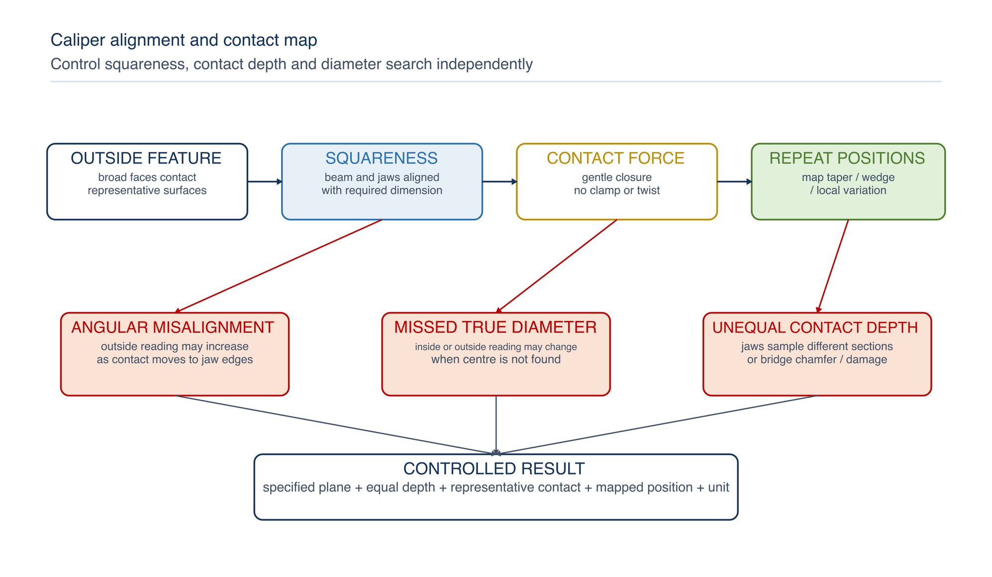
Measure outside features with a caliper
Use this sequence:
- open the jaws wider than the feature;
- place the broad measuring faces on clean representative surfaces;
- align the beam and jaws square to the required dimension;
- close gently until both faces contact without visible gap or part deformation;
- make a small controlled alignment search where needed;
- stabilise the contact without using the lock to force the jaws tighter;
- read without twisting the caliper; and
- repeat at the specified positions.
For an outside diameter, a reading that is too high may result from angular misalignment; a reading that is too low can result from missing the true diameter or contacting local damage. Search deliberately in the required plane and retain meaningful variation rather than selecting the preferred number.
Measure inside features with a caliper
Inside-jaw measurements are sensitive to jaw-tip geometry, jaw depth, alignment, hole size, wear and operator feel.
For an accessible bore:
- insert the inside jaws without striking the edge;
- keep both contacts at the same required depth;
- orient the caliper in the specified measurement plane;
- open gently until both faces contact;
- rock through the diameter in one direction and sweep through the centre in the perpendicular sense as appropriate;
- identify the true-diameter position rather than the first stable reading;
- avoid tilting one jaw deeper than the other; and
- repeat in required planes and depths to reveal taper or ovality.
Small, shallow, chamfered, rough, interrupted or deep holes may not provide representative contact for ordinary inside jaws. Use a bore gauge, inside micrometer, plug or ring system, coordinate method or other specified process when required.
Measure depth and steps from the intended datum
For depth measurement:
- clean the reference surface and feature bottom;
- place the caliper end or designated reference surface fully on the datum;
- avoid rocking across a narrow edge, radius, chamfer or burr;
- extend the depth rod along the intended axis;
- contact the bottom gently without bending the rod or lifting the reference; and
- repeat across the feature if the requirement concerns variation rather than one local point.
For step measurement, use only the step faces designed for the instrument. Confirm that both faces contact the intended shoulders and are not held apart by corner radii, coatings or damage.
Use an outside micrometer correctly
An outside micrometer is suited to opposed external faces when the contact geometry and documented instrument characteristics support the task. Use this sequence:
- confirm the correct range and setting reference;
- clean the anvil, spindle and workpiece surfaces;
- open the spindle beyond the feature;
- place the part between the faces without striking or scraping it;
- align the spindle axis with the required dimension;
- advance using the thimble until near contact;
- complete contact with the constant-force device in the instrument's specified manner;
- maintain alignment while the force stabilises;
- lock only when the method requires it and without shifting the reading;
- read in position where practical; and
- withdraw before sliding the faces across the part.
Do not spin the thimble rapidly into the work, use the micrometer as a clamp, force the spindle with the frame, or drag precision faces across an abrasive surface.
Control alignment and measuring force together
Alignment error and force error can interact. Excessive force may flatten contamination, deform the part, flex the frame or make a misaligned contact appear stable. Insufficient or inconsistent force may leave incomplete contact.
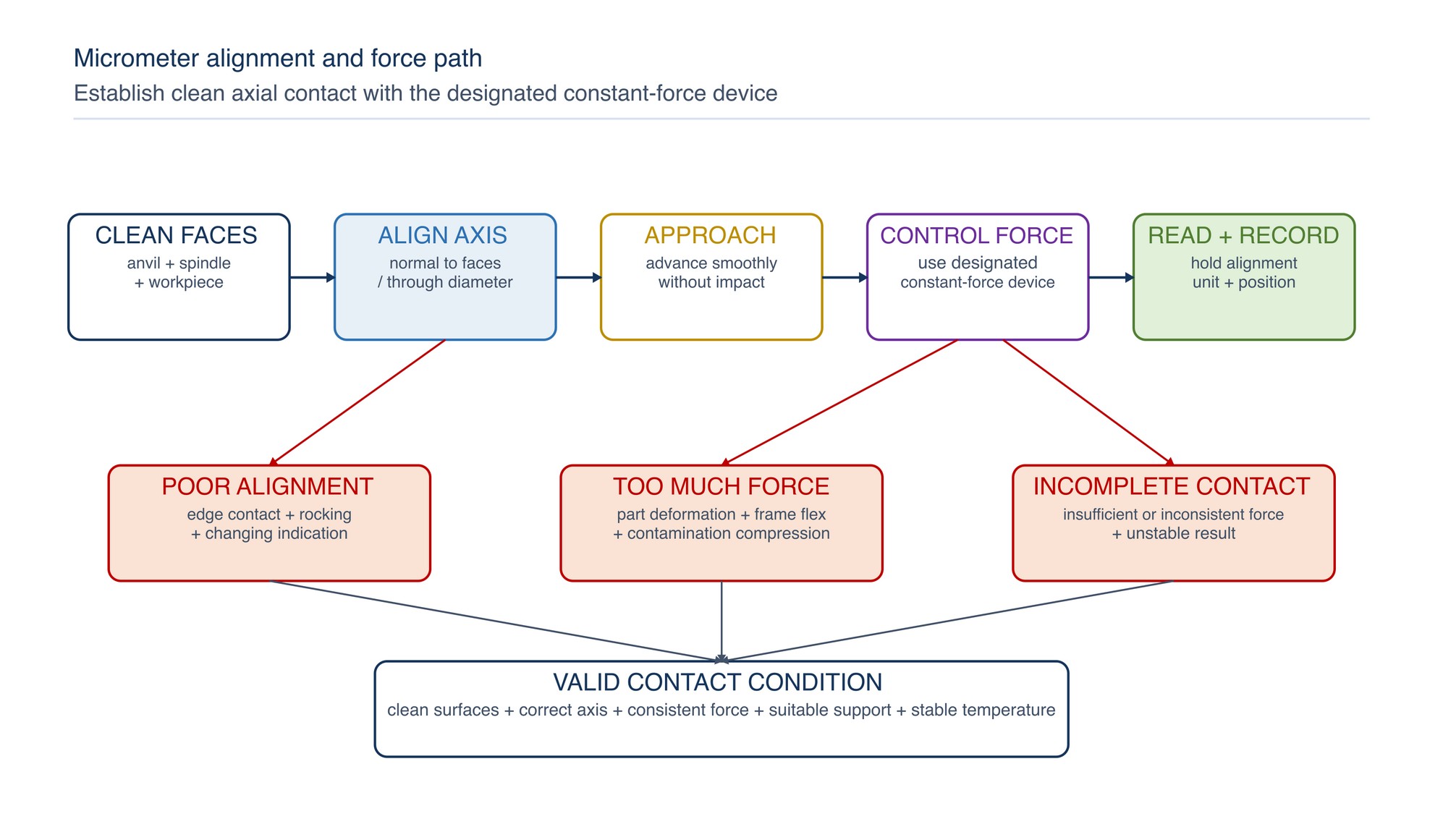
Control the following:
| Influence | Practical control | Warning sign |
|---|---|---|
| Axial alignment | Keep anvil and spindle normal to parallel surfaces or through the true diameter | Reading changes as the frame is rocked |
| Measuring force | Use the designated constant-force device consistently | Reading changes with operator grip or repeated clicks |
| Face condition | Keep faces clean, undamaged and appropriate to the feature | Unstable contact or light visible at one side |
| Part support | Hold or fixture without heating or deforming the feature | Reading changes when grip or support changes |
| Surface geometry | Avoid bridging radii, burrs, rough peaks or local dents | Repeated values differ by contact position |
Protect soft, thin, flexible and sensitive workpieces
Contact measurement can change the dimension being measured. Take particular care with:
- thin sheet, foil, tubing and soft polymers;
- rubber, coatings, seal materials and laminated products;
- hot parts and materials with high thermal expansion;
- flexible shafts, long bars and lightly supported components;
- very rough, porous or compressible surfaces; and
- finished surfaces susceptible to scratching or indentation.
Use the specified force-controlled contact, support and method. If the ordinary caliper or micrometer changes the part, contacts only roughness peaks or cannot represent the specified material condition, route the task to a suitable low-force, dedicated-contact or non-contact process.
Repeat at positions that answer the requirement
Repeated readings are useful only when their positions are defined. For a cylindrical feature, measure in specified angular planes and at meaningful axial stations. For parallel faces, compare positions that can reveal taper, wedge or local wear. For sheet or plate, define edge distance and support.
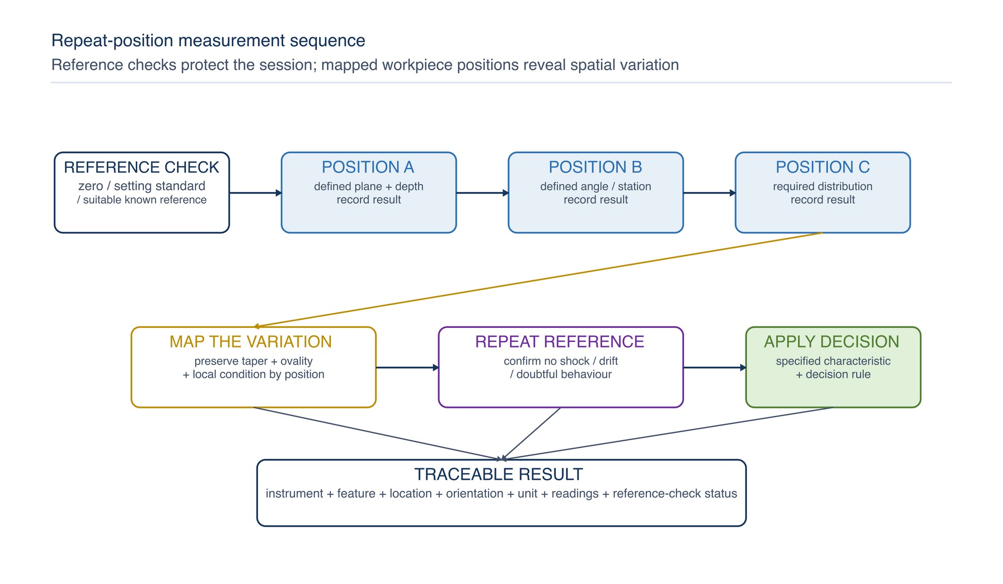
Do not average away taper, ovality or local variation when the drawing controls an extreme or geometrical characteristic. Record the mapped results or the required derived value using the approved inspection method.
Use zero and known-reference checks correctly
Apply checks appropriate to the instrument and task:
- clean-face zero or setting check;
- supplied setting standard for the relevant micrometer range;
- suitable calibrated gauge block, ring, setting master or other reference;
- checks near the measurement region when required;
- internal, depth or step checks that exercise the relevant contact function; and
- repeat checks after shock, temperature change, doubtful behaviour or a measurement session.
Gauge blocks are controlled length standards with their own grade, condition, calibration status and uncertainty. Select references through the measurement system; do not treat any convenient object as a calibration standard. [S254; S256]
| Check | What it establishes | What it does not establish by itself |
|---|---|---|
| Clean-face zero or setting check | Indication at the closing or defined setting condition | Performance through the range or every measuring function |
| Supplied micrometer setting standard | Setting response for the applicable range and reference | Workpiece suitability, alignment or measuring uncertainty |
| Suitable calibrated length reference | Response at a controlled value and stated condition | Complete calibration unless the authorised process defines it so |
| Internal, depth or step reference | Behaviour of the specific contact function being used | Capability for a different jaw, rod, range or feature geometry |
| End-of-session repeat reference | Evidence that the checked condition remained stable during the session | Proof that every workpiece contact and recorded position was correct |
If the instrument fails a required check, isolate it from acceptance work and follow the authorised verification, adjustment, calibration or repair route. Do not adjust repeatedly until one reading agrees.
Clean, store and transport the instrument correctly
After use:
- remove chips, dust, coolant and fingerprints with an approved method;
- leave precision faces clean, dry and protected as specified;
- do not store a micrometer tightly closed unless its instructions require it;
- release locks and avoid loading the slider, depth rod, spindle or frame;
- place the instrument in its protective case or controlled cabinet;
- separate it from grinding dust, welding spatter, corrosive chemicals, moisture, impact and magnetic or electrical hazards as applicable;
- do not mark measuring faces with scribers, stamps or abrasive cleaners; and
- report shock, dropping, sticking, corrosion, unstable indication, battery leakage or damaged contacts before reuse.
Measurement-management controls should keep equipment fit for its intended process and provide confidence in the validity and reliability of results. [S254]
Troubleshoot inconsistent readings
| Observation | Likely causes | Practical correction |
|---|---|---|
| Outside caliper reading increases when tilted | Jaws not square or contact on an edge | Re-establish the specified plane and square broad-face contact |
| Bore reading changes widely with position | Missed true diameter, unequal jaw depth, taper or ovality | Define plane and depth; search through the centre and map positions |
| Depth reading changes when hand pressure changes | Reference surface rocking or depth rod not axial squarely | Clean and fully seat the reference; support |
| Micrometer reading falls with greater force | Soft material, contamination or frame/part deformation | Use the specified force method and suitable support or alternative process |
| Micrometer reading changes while rocking | Measuring faces not aligned with the feature | Search for correct axial alignment without excessive force |
| Zero passes but known reference fails | Wear, damage, scale error, temperature difference or incorrect reference | Isolate the instrument and follow the controlled use verification route |
| Digital value jumps or changes | Contamination, low battery, reference-mode or unit control error | Stop, clean, confirm power, unit and reference setting, then re-check |
| Vernier or dial readings differ by operator | Parallax, reading sequence, dial revolution or alignment variation | Standardise viewing, reading and contact technique; use a known reference |
| Repeated readings differ only at mapped positions | Genuine taper, ovality, roughness or local damage | Preserve the positional results and evaluate the specified characteristic |
| Near-limit result cannot support a clear decision | Instrument/process uncertainty is significant | Apply the controlled decision rule or route to a more capable process |
Practical measurement and release checklist
Before releasing the result, confirm:
- the correct part, feature, drawing and revision were used;
- the characteristic, location, orientation, unit and limits were clear;
- the selected instrument and contact geometry suited the task;
- instrument identity, status, range and indication mode were confirmed;
- measuring faces and workpiece contacts were clean and undamaged;
- burrs, chamfers, radii, coatings, roughness and local damage were considered;
- the instrument, workpiece and reference were sufficiently temperature stable;
- the workpiece was supported without deformation;
- the required zero and known-reference checks passed;
- outside caliper jaws were square and used with controlled force;
- inside caliper jaws found the true diameter at the specified plane and depth;
- depth and step references were fully seated on the intended datum;
- micrometer faces were aligned and the constant-force device was used consistently;
- the indication was read in the correct unit and mode without unsupported digits;
- mapped repeat positions answered the drawing requirement;
- genuine taper, ovality or local variation was not averaged away;
- instrument, location, orientation, unit, result and relevant conditions were recorded;
- near-limit or doubtful results followed the applicable decision route; and
- the instrument was cleaned, protected and returned to controlled storage.
Calibration and Measurement Control
The Calibration and Measurement Control chapter appears on the following page of the printed handbook (page 374), outside this chapter extract.