
Production operators, fabricators, grinding and finishing teams, inspectors, supervisors, quality personnel, maintenance personnel and technical sales personnel
Practical workshop measurement of size, depth, height, gap, radius, thread and simple geometric variation, from drawing interpretation and instrument selection through setup, repeat checks, recording and conformity decisions.
Stop and isolate moving equipment as required by the safe system of work; never place a hand instrument against a rotating or moving workpiece. If a measuring face is chipped, loose, visibly worn or contaminated, remove the instrument from use under the site's measurement-control process. Do not polish, stone, bend or adjust precision measuring faces unless the authorised procedure allows it.
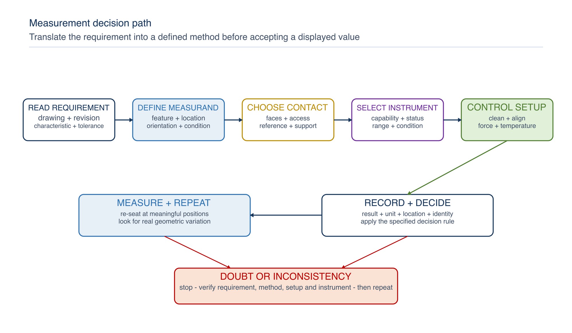
Core principle - Measure the specified characteristic, at the specified location and orientation, with an instrument and method capable of supporting the decision. A clear display is not proof that the correct feature has been measured correctly.
Dimensional measurement connects manufacturing intent to an observed result. The drawing defines what matters; the workpiece, instrument, environment and operator determine how reliably it can be assessed. Good practice begins before the instrument touches the part: define the measurand, select the contact method, prepare the surfaces, control alignment and force, repeat at meaningful positions, and record enough information for another competent person to understand the result. [S230; S231; S237; S238]
Chapter objectives
After this chapter, the reader should be able to:
- identify the actual characteristic required by a drawing, inspection plan or work instruction;
- distinguish size from form, orientation, location, surface texture and comparative gauging;
- select a suitable basic instrument by feature access, tolerance, contact geometry and required decision;
- distinguish display resolution from accuracy, precision, calibration status and measurement uncertainty;
- prepare the workpiece, reference surfaces and measuring faces before measurement;
- control support, alignment, seating, contact position and measurement force;
- recognise temperature, dirt, burrs, coating, roughness, compliance and hand heat as possible influences;
- repeat measurements at positions that can reveal taper, ovality, bow and local variation;
- use zero and known-reference checks without confusing them with calibration;
- record the characteristic, location, unit, instrument identity and result clearly;
- treat results close to a specification limit through the applicable decision rule; and
- stop when the setup, instrument condition or result is not trustworthy.
Begin with the requirement, not the instrument
Read the complete drawing callout, note or inspection instruction before choosing a tool. A nominal dimension by itself is incomplete: the tolerance, datum or reference surface, feature boundaries, units, modifier, sampling requirement and acceptance rule may change the measurement method.
Ask four questions:
- What characteristic is specified: outside size, inside size, depth, step, height, gap, radius, thread, form, orientation, location or surface texture?
- Which exact surfaces, points or feature boundaries define it?
- In which direction and at which location must it be measured?
- What decision must the result support: setup, process adjustment, comparative sorting, in-process control or final acceptance?
The same two surfaces can produce different results when measured at different heights, angular positions or distances from an edge. A diameter can vary along its length and around its circumference; a plate can have acceptable local thickness but excessive bow; a hole can have a displayed diameter while its axis location remains unverified. Do not substitute an easy measurement for the specified characteristic. [S230; S235]
Define the measurand clearly
The measurand is the quantity intended to be measured. In workshop language, it is the precise answer to: “What dimension, at what place, in what direction, under what condition?” [S230; S238]
Compare these descriptions:
- “shaft diameter” is broad;
- “outside diameter at the bearing seat” is better;
- “outside diameter at three axial stations, measured in two angular orientations after temperature stabilisation” defines a repeatable measurement task.
A complete definition avoids accidental changes between operators, shifts or suppliers. It also makes variation meaningful: different readings may represent real workpiece geometry rather than instrument inconsistency.
| Requirement family | What it describes | Basic workshop approach | Important boundary |
|---|---|---|---|
| Linear size | Distance associated with opposed surfaces, a cylinder or another specified feature of size | Rule, calliper, micrometer or dedicated size gauge | A size reading does not automatically establish form, position or orientation |
| Depth or step | Distance from a defined reference surface to a lower or higher feature | Depth gauge, depth micrometer, calliper depth rod or height-based method | The base must seat on the intended datum without rocking or bridging |
| Height | Distance from a reference plane to a feature | Height gauge on a suitable surface plate or controlled reference | Reference-plane condition and probe geometry affect the result |
| Gap or clearance | Separation between assembled or adjacent surfaces | Feeler gauges or another suitable contact method | Access force and surface damage can change the apparent gap |
| Radius or profile | Comparison of a contour with a specified form | Radius gauge, profile template or optical/profile method | A light-gap comparison is not a complete numeric radius measurement |
| Thread | Pitch, form, major/minor/pitch diameter or functional fit as specified | Pitch gauge, thread plug/ring gauge or dimensional method | Pitch identification alone does not prove functional thread acceptance |
| Form, orientation or location | Straightness, flatness, roundness, perpendicularity, position or related geometry | Indicator, comparator, surface plate, dedicated fixture or suitable measuring system | A calliper or micrometer reading alone normally cannot establish the full requirement |
| Surface texture | Roughness, waviness, lay or another specified texture characteristic | Suitable surface-texture instrument and method | Visual smoothness and dimensional size are different properties |
Use measurement terms correctly
Clear terminology prevents false confidence. A digital display may show many digits, but the number of digits is not the same as the quality of the result. [S231; S238]
| Term | Practical meaning | What it does not mean |
|---|---|---|
| Indication | The value shown or indicated by the instrument | Automatically the final measurement result |
| Resolution | The smallest change the display or scale can distinguish | Accuracy, capability or uncertainty |
| Accuracy | Qualitative closeness between a measured value and the value of the measurand | A numerical specification that can be read directly from display resolution |
| Precision | Closeness of agreement among repeated indications under specified conditions | Freedom from systematic error |
| Repeatability | Precision under defined repeat conditions such as same method, operator, instrument and location | Agreement between different methods or laboratories |
| Measurement uncertainty | A parameter describing the dispersion of values attributed to the measurand from the information used | A mistake allowance or automatic reason to reject a result |
| Calibration | Establishing the relation between standards and instrument indications, with associated uncertainties, so results can be obtained from indications | Cleaning, zeroing, adjustment or a quick shop-floor check |
| Verification | Confirmation that specified requirements have been fulfilled | A substitute for a suitable measurement method |
Do not say that an instrument is “accurate to its last digit” merely because the display is stable. For the exact instrument range, resolution, permissible error, environmental rating or metrological characteristics, Refer to the product label, Technical Data Sheet, or MKTECH representative. [S231; S232; S233; S234]
Select the instrument by feature, access and decision
Choose the contact geometry first, then the instrument. The measuring faces must reach the intended feature, contact it in a controlled way and avoid bridging, rocking or touching adjacent geometry. The instrument's documented characteristics must support the required tolerance and decision. [S231; S237]
| Instrument or gauge | Best suited to | Strengths | Common limitations or misuse |
|---|---|---|---|
| Steel rule | Approximate length, layout confirmation and generous-tolerance checks | Fast, robust and easy to apply | Parallax, end wear, line width and poor edge definition limit close decisions |
| Calliper | General outside, inside, step and depth measurements where its capability is suitable | Versatile and quick for workshop checks | Jaw wear, access, alignment and variable hand force can dominate the result |
| Outside micrometer | Controlled measurement of accessible outside sizes | Rigid frame, defined measuring faces and controlled-force features on suitable models | Narrower function; heat, alignment, anvil condition and overtightening still matter |
| Depth gauge or depth micrometer | Holes, slots, recesses and steps measured from a reference surface | Broad base can establish a defined reference plane | Base rocking, burrs, edge chamfers and bottom geometry can create false readings |
| Height gauge | Heights, steps, scribed locations and comparative checks from a reference plane | Useful for repeated work on a controlled surface | Surface plate, base cleanliness, probe alignment and part support are critical |
| Bore gauge or internal comparator | Internal diameter and variation at selected depths and directions | Sensitive to taper and ovality when correctly set and rocked | Usually requires a suitable reference setting and disciplined technique |
| Feeler gauge | Accessible gaps and clearances | Direct, simple comparative assessment | Blade drag, stack condition, access angle and part compliance affect interpretation |
| Radius gauge | Quick comparison of convex or concave radii | Useful for profile identification and gross mismatch detection | Light-gap judgement is operator dependent and not a full numeric profile measurement |
| Thread pitch gauge | Identifying or comparing thread pitch and form | Rapid matching aid | Does not by itself verify thread diameter, lead, flank condition or functional fit |
| Thread plug or ring gauge | Functional limit assessment of specified internal or external threads | Fast pass/fail control when gauge and method are correct | Does not report the actual dimension and must match the thread system and requirement |
Prefer an instrument that makes correct alignment and contact easy. A higher-resolution instrument is not automatically better if its faces cannot reach the feature, the workpiece deforms under contact, or the setup introduces a larger error.
Detailed calliper and micrometer technique is covered in Chapter 043; calibration-system control is covered in Chapter 044.
Prepare the workpiece and instrument
Measurement begins with clean, serviceable contact surfaces. Loose dirt, abrasive grain, oil film, paint flakes, corrosion product or swarf can hold the instrument away from the true surface. Burrs, raised edges and impact marks may be part of the manufactured condition or may be unwanted damage; do not remove them casually before understanding the inspection requirement.
Before use:
- Stop and isolate moving equipment as required by the safe system of work; never place a hand instrument against a rotating or moving workpiece.
- Confirm the instrument identity, status, measuring range and suitability for the feature.
- Inspect measuring faces, jaws, tips, base and slides for dirt, damage, wear or looseness.
- Clean the workpiece and reference surfaces with a method that will not scratch, distort or heat them.
- Check that the feature is accessible without forcing the instrument or contacting adjacent geometry.
- Confirm zero or the appropriate reference condition, then check a suitable known reference where the task requires it.
If a measuring face is chipped, loose, visibly worn or contaminated, remove the instrument from use under the site's measurement-control process. Do not polish, stone, bend or adjust precision measuring faces unless the authorised procedure allows it.
Control temperature and the environment
Dimensional properties are specified with reference to a standard reference temperature, and real materials change size with temperature. Instrument and workpiece temperature, temperature gradients, hand heat, recent machining, sunlight and air movement can therefore influence the result. [S230; S237; S239]
The practical control depends on material, size, tolerance and required uncertainty. A rough fabrication check may tolerate conditions that are unsuitable for a close final inspection. Bring the workpiece, instrument and reference standard into a sufficiently stable condition for the required decision. Avoid measuring a hot component directly after grinding, welding, machining or washing when thermal change can be significant.
Use insulating pads, supports or gloves only where they do not contaminate, deform or destabilise the setup. Hold precision instruments by their intended insulating surfaces where provided and avoid prolonged contact with the frame or measuring faces. Do not apply an assumed thermal correction unless the material, temperatures, method and uncertainty treatment are controlled.
Where exact stabilisation time, reference correction or environmental limit is needed, Refer to the product label, Technical Data Sheet, or MKTECH representative.
Support the workpiece without changing it
A dimension can change when a thin, long, soft or flexible part is clamped, lifted or placed on an uneven surface. Support must make the feature accessible without bending, twisting or masking the condition being measured.
For long parts, choose support points that minimise sag for the characteristic of interest. For thin sheet, do not squeeze the measuring faces hard enough to flatten local waviness unless the specified method defines that condition. For soft coatings, plastics, elastomers and thin-wall sections, consider whether the contact force or support can compress the material.
Keep the datum or reference surface clean and fully seated. A chip under one corner can tilt the entire part. If a part rocks, determine whether the cause is dirt, burrs, unstable support or actual form variation before recording a result.
Align the measurement axis and contact faces
The instrument axis must follow the intended dimension. Angular misalignment creates cosine-type error; an offset between the measurement scale and the line of measurement can amplify angular effects; incomplete seating or contact on a radius can shift the apparent boundary. [S231; S237]
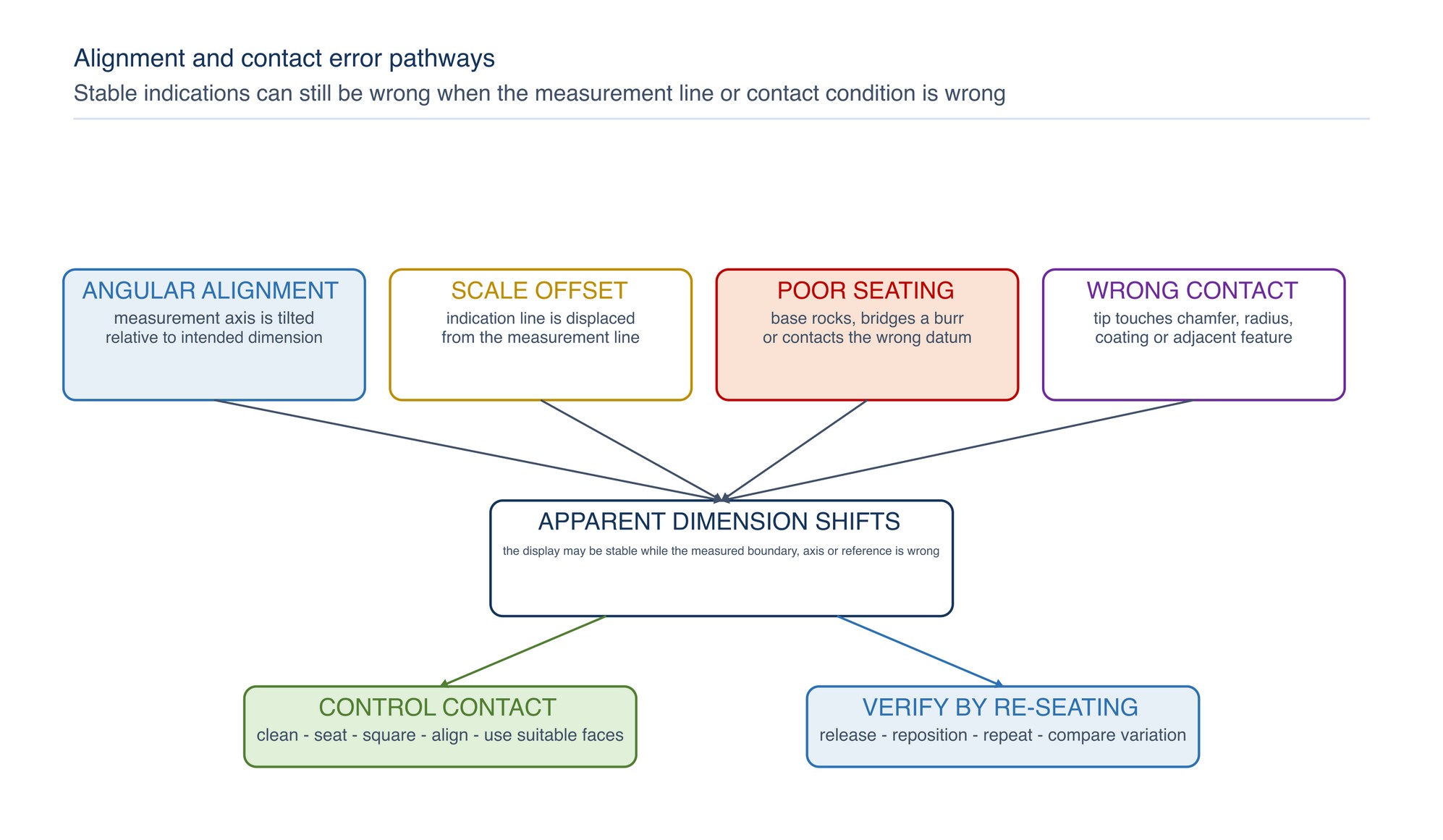
Use these controls:
- keep measuring faces square to flat surfaces;
- seek the true diameter across a cylinder rather than a chord;
- use a gentle rocking or sweeping method only where appropriate to find the intended maximum or minimum contact condition;
- seat depth-gauge bases fully on the reference surface without bridging an edge or burr;
- keep long jaws or extensions aligned and avoid side loading;
- confirm that chamfers, radii, weld spatter, coating build-up or edge break are not being mistaken for the defined feature boundary; and
- repeat after releasing and re-seating the instrument rather than trusting one carefully “held” reading.
Do not force a stable number. If the reading changes with slight, legitimate repositioning, investigate geometry, support, access and technique.
Apply consistent and appropriate contact force
Contact force must be sufficient to establish repeatable contact but not so high that it deforms the part, bends the instrument, marks the surface or squeezes out a compliant layer. Force is especially important for soft materials, thin sections, coated surfaces, narrow contacts and hand-operated callipers. [S237]
Use the instrument's controlled-force device when provided and suitable for the method. With a micrometer, do not use the frame as a clamp or tighten past the controlled-contact action. With a calliper, use light, consistent thumb pressure and confirm that the slide is not being skewed. With feeler gauges, interpret drag consistently and avoid forcing a blade into a gap that damages the part or changes the clearance.
A repeated number obtained with excessive force is still a poor result. If different trained operators need substantially different force to obtain agreement, the method may require better fixturing, a more suitable instrument or a defined force-control approach.
Measure outside size correctly
For an outside width, thickness or diameter, contact the intended surfaces with clean, parallel measuring faces. Approach the part without impact. Align the instrument, establish contact using consistent force and observe whether slight repositioning changes the reading.
For a shaft or round feature, measure at more than one angular orientation and at suitable axial positions. This can reveal ovality, taper, barrel shape, local wear or surface damage. For sheet or plate, select positions that represent the requirement and avoid assuming an edge reading represents the full part.
Do not measure over loose scale, weld spatter or a burr unless the requirement intentionally includes it. If a coating is present, establish whether the drawing dimension applies before coating, after coating or to the substrate. The answer changes both the measurand and the instrument contact condition.
Measure inside size, depth and height correctly
Internal measurement is sensitive to access and contact geometry. Calliper inside jaws may contact a chord instead of the true diameter; worn knife edges can bias small internal measurements; bore gauges require correct setting and alignment. Use a method suited to the feature depth, diameter, surface condition and tolerance. [S232; S237]
For a hole or bore:
- measure at specified or meaningful depths;
- check at more than one angular orientation;
- keep the measuring axis perpendicular to the bore axis unless another condition is specified;
- avoid contacting chamfers, damaged edges, grooves or debris; and
- use a suitable comparative or direct-reading internal instrument when the calliper contact geometry is inadequate.
For depth, the base must sit flat on the specified reference surface. Keep the rod or spindle aligned with the depth direction and ensure the tip contacts the intended bottom—not a radius, chip, angled surface or accumulated debris. For height, keep the reference plane, instrument base and workpiece support clean and stable; approach the feature without side loading the probe.
Use comparative gauges within their purpose
Comparative gauges answer a defined comparison question. They may confirm fit, pitch, gap or profile without reporting the actual dimension.
Use a feeler gauge only when the selected blade or stack can enter along the intended path without forcing the assembly apart. Keep blades clean, flat and free from kinks or raised damage. Record the assessment method when “light drag” or a similar tactile condition is part of the procedure.
Use a radius gauge by comparing both the centre and edge light gaps at a clean profile. A good visual fit at one location does not establish the complete three-dimensional form. Use thread pitch gauges for pitch/form identification and plug or ring gauges for their defined functional limit decision. Do not use a thread gauge as a tap, die, scraper or alignment tool.
When the gauge identity, wear status, temperature or application is uncertain, stop and verify it through the site's measurement-control system.
Repeat at positions that reveal real variation
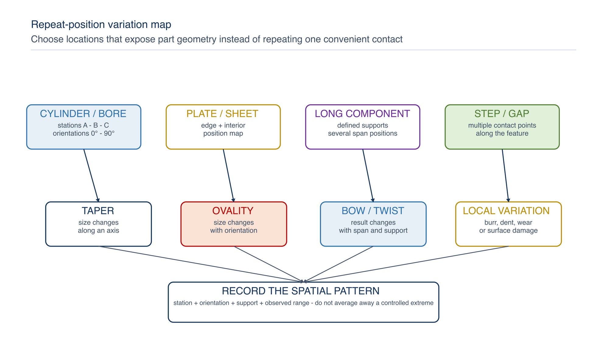
Repeating the same contact at the same place mainly tests immediate repeatability. To understand the part, move to positions and orientations that can reveal its likely geometric variation. [S237; S238]
| Feature | Useful repeat pattern | Variation that may appear | Recording cue |
|---|---|---|---|
| Shaft or pin | Several axial stations and at least two angular orientations | Taper, ovality, barrel shape, wear or local damage | Record station and orientation with each result |
| Hole or bore | More than one depth and angular orientation | Taper, bell-mouth, ovality, tool marks or local damage | Identify depth from the selected face and measurement direction |
| Plate thickness | Edge and representative interior locations as specified | Thickness variation, edge roll, coating build-up or local dents | Use a position map or coordinates for important parts |
| Long straight component | Defined support condition and several positions | Bow, twist, sag or local deformation | Record support arrangement and measurement direction |
| Step or recess | Several points across the base or face | Tilt, uneven bottom, burr or seating error | Record the reference surface and contact positions |
| Gap or clearance | Defined positions around or along the assembly | Misalignment, taper, distortion or local interference | Record assembly condition and gauge orientation |
If variation is greater than expected, do not average it away automatically. The drawing may control maximum local size, least size, form or another characteristic for which the extreme or spatial pattern matters. Escalate unclear interpretation before making a conformity decision.
Check zero and a suitable known reference
A zero check confirms one condition at or near zero. It can reveal dirt, incomplete closure, obvious damage or an incorrect reference setting, but it does not demonstrate performance throughout the measuring range. A suitable known-reference check can provide stronger evidence near the working size, provided the reference is identified, in status and used correctly. [S237; S238]
Clean the reference and measuring faces before the check. Use a reference type and size appropriate to the instrument and measurement. Record significant check failures and remove the instrument from use when required. Do not adjust an instrument merely to make one reference agree if the cause may be wear, damage, temperature or an incorrect technique.
Calibration establishes a documented relation using measurement standards and uncertainties. A shop-floor comparison, zero setting or button labelled “cal” is not automatically calibration. [S238]
Record a result another person can understand
A useful record identifies what was measured and how. Do not record unsupported decimal places simply because the display provides them.
Include, as appropriate:
- part, job, drawing and revision identity;
- characteristic and nominal/tolerance requirement;
- measurement location, depth, station, orientation and datum or reference surface;
- result and unit;
- instrument or gauge identity;
- method or fixture identity where it affects interpretation;
- environmental or temperature condition where significant;
- operator and date/time where required;
- repeated values or observed range where variation matters; and
- decision rule, acceptance status or escalation reference where required.
Use a position sketch for complex parts. “Diameter 25.00” is not enough when the part has several diameters or the value varies along its length. Keep the original observed values available when a calculated average, correction or summary is reported.
Make conformity decisions with the applicable rule
A displayed value inside the nominal tolerance is not always sufficient for acceptance. The result, method capability, measurement uncertainty and applicable decision rule matter, especially close to a specification limit. ISO 14253-1 addresses uncertainty-aware rules for verifying conformity and nonconformity of workpiece characteristics and measuring equipment. [S236]
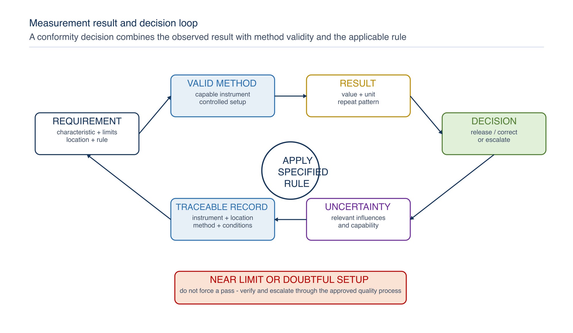
Use this practical logic:
- Confirm the requirement and measurement method are valid for the characteristic.
- Confirm instrument status, setup and reference checks are acceptable.
- Review repeated readings and spatial variation for evidence of setup or part-condition problems.
- Compare the measurement result with the specification using the stated decision rule.
- Escalate a result near a limit when uncertainty can affect the decision.
- Record the decision and retain the supporting measurement information.
Do not invent a guard band, subtract uncertainty informally or round a value to create acceptance. Do not change instrument or operator repeatedly until one reading passes. If the required decision rule is not stated, use the organisation's approved inspection and quality procedure.
Troubleshoot doubtful measurements
| Observation | Likely causes | Practical correction |
|---|---|---|
| Reading changes when the instrument is tilted off-axis | Angular misalignment, chord measurement or contact | Re-establish the intended measurement axis and use contact geometry suited to the feature |
| Reading changes with hand pressure | Variable force, part compliance, loose slide or instrument flex | Use consistent controlled force, improve support and select a more suitable instrument if needed |
| Zero is unstable or does not repeat | Dirt, damaged faces, temperature change, loose mechanism or low power on an electronic instrument | Clean and inspect; verify condition and remove from use if the fault remains |
| Different operators obtain different results | Measurand, location, alignment, force or tactile criterion is not sufficiently defined | Clarify the method, mark locations, standardise technique and verify with a suitable reference |
| Bore reading differs by direction | Ovality, alignment error, worn contacts or surface damage | Repeat at defined angular positions and depths with a suitable internal method |
| Depth reading varies across the opening | Base rocking, burr, debris, angled bottom or real form variation | Clean and seat the base; map positions and identify the actual bottom condition |
| Measurement drifts after handling | Hand heat, workpiece cooling, instrument warming or electronic instability | Stabilise conditions, reduce handling and repeat after a controlled interval |
| Result is close to the tolerance limit | Normal variation, uncertainty, rounding or inadequate method capability | Apply the specified decision rule and escalate rather than forcing a pass/fail conclusion |
| Surface is rough and readings scatter | Contact tips bridge peaks and valleys or touch different local points | Define the contact method and locations; use a method appropriate to the specified characteristic |
| Gauge passes in one location but fails elsewhere | Taper, bow, ovality, burr, distortion or local damage | Map the feature and compare the spatial pattern with the actual drawing requirement |
Practical measurement and release checklist
Before releasing the result, confirm:
- the current drawing, revision and complete characteristic requirement were used;
- the measurand, location, orientation and reference surface are clear;
- the selected instrument can contact the feature correctly and supports the required decision;
- instrument identity, status, range and condition were checked;
- measuring faces, reference surfaces and the workpiece were clean and serviceable;
- the workpiece and instrument were sufficiently temperature stable;
- the part was supported without bending, twisting, heating or masking the characteristic;
- alignment, seating, contact position and measurement force were controlled;
- zero and any required known-reference check were satisfactory;
- measurements were repeated at positions that can reveal relevant variation;
- the unit, location, instrument identity and observed result were recorded without false precision;
- any result near a limit was handled through the applicable uncertainty-aware decision rule; and
- doubtful setups, damaged instruments and inconsistent results were escalated rather than accepted by convenience.
Surface and Weld Inspection
The next chapter, Surface and Weld Inspection, appears on the following page of the printed handbook (page 354), outside this chapter extract.