
Production managers, quality personnel, inspectors, fabricators, grinding and finishing teams, supervisors, maintenance personnel, technical sales personnel and personnel who prepare industrial reports
Practical photography for documenting abrasive applications, surface condition, welds, components, equipment and inspection findings, including planning, site safety, camera position, image sequence, focus, lighting, reflections, scale references, colour limitations, file control, repeat photography, reporting and troubleshooting.
Do not step into a danger zone, remove a guard, lean over rotating equipment or defeat an interlock to obtain a better angle. Use a safe viewpoint, zoom or suitable remote support when the required view can be obtained without approaching the hazard. If access requires isolation, follow the site’s authorised energy-control and verification procedure. Photography never creates an exception to machine guarding, work-at-height, confined-space, hot-work, chemical, electrical or traffic controls. [S272] In an explosive atmosphere or classified hazardous area, do not assume that a phone, camera, battery, lamp or accessory is acceptable. Equipment selection must match the area classification, protection requirements and site authorisation. [S273]
An inspection photograph is useful when a reviewer can identify the item, locate the feature, see the relevant detail and understand the capture conditions without being misled by glare, perspective, processing or an incomplete view.
Photography can preserve condition, support communication and make comparisons easier. It does not replace the applicable inspection method, acceptance criteria or competent judgement. A sharp close-up without context may be impossible to locate; a ruler placed at a different depth may suggest a false size; and an attractive image may hide the very feature being inspected. A controlled sequence is therefore more valuable than a single dramatic photograph. [S265; S267; S274]
Chapter objectives
After this chapter, the reader should be able to:
- define the purpose and required views before capture;
- perform photography without entering a danger zone or disturbing the condition being documented;
- capture location, context, item, feature and close-detail views in a logical sequence;
- identify the item, orientation and feature without obscuring relevant evidence;
- select suitable field of view, working distance, camera support, focus and depth of field;
- choose lighting geometry for shape, texture, scratches, contamination and reflective surfaces;
- use a clean scale as a size reference while recognising perspective and calibration limits;
- control colour appearance and avoid treating uncontrolled images as absolute colour measurements;
- preserve original files, metadata and an understandable file relationship;
- annotate controlled copies while retaining an unchanged original;
- repeat photographs in a way that supports meaningful comparison; and
- troubleshoot common failures before releasing an inspection report.
Start with the inspection question
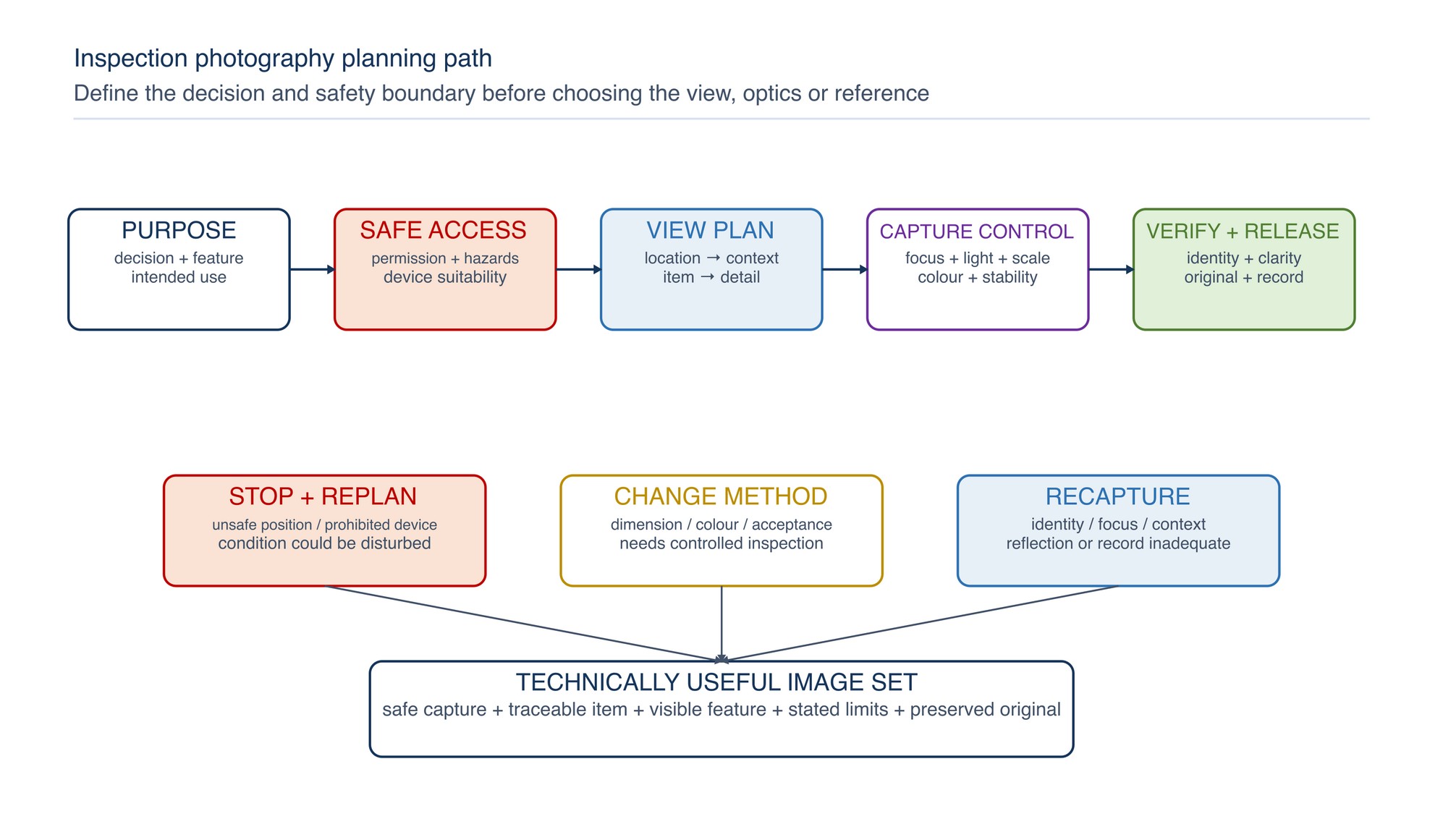
Before selecting a camera, define what the image must help a reviewer decide. Typical purposes include:
- locating a defect or process area;
- documenting pre-work and post-work condition;
- showing an abrasive product in use without implying a performance test;
- recording surface contamination, heat tint, scratches, gouges, coating failure or weld profile;
- supporting a maintenance, warranty or technical-service discussion;
- comparing condition at two controlled stages; or
- showing an installation, access or guarding issue.
Write a short image requirement: item identity, feature, orientation, required detail, scale context, lighting condition and intended use. If a dimension, colour difference or acceptance decision is critical, specify the separate controlled measurement or inspection method that will provide it. Photography then documents the condition and the measurement location rather than carrying more authority than the imaging process can support. [S265; S266; S268]
Make safety the first camera setting
Do not step into a danger zone, remove a guard, lean over rotating equipment or defeat an interlock to obtain a better angle. Use a safe viewpoint, zoom or suitable remote support when the required view can be obtained without approaching the hazard. If access requires isolation, follow the site’s authorised energy-control and verification procedure. Photography never creates an exception to machine guarding, work-at-height, confined-space, hot-work, chemical, electrical or traffic controls. [S272]
Before capture, confirm:
- site permission and the responsible contact;
- area hazards and required PPE;
- whether equipment must be stopped, isolated, cooled or cleaned;
- whether the photographer can remain outside guarded or restricted zones;
- whether flash, lamps, tripods, cables or magnetic mounts create a new hazard;
- whether the camera could contaminate a clean process or be contaminated by the process;
- whether people, screens, labels or drawings contain confidential or personal information; and
- whether the device is permitted in the area.
In an explosive atmosphere or classified hazardous area, do not assume that a phone, camera, battery, lamp or accessory is acceptable. Equipment selection must match the area classification, protection requirements and site authorisation. [S273]
Protect the condition being documented
Photograph the as-found condition before cleaning, repositioning, marking, measuring or repair where that condition matters. Avoid touching deposits, smearing contamination, dislodging fragments or placing a dirty scale on a sensitive surface. Use clean barriers and handling controls appropriate to the item.
If cleaning is required to reveal a feature, record the sequence clearly:
- overall condition before cleaning;
- close view before cleaning;
- cleaning method or prepared state, where relevant;
- the revealed feature after cleaning; and
- any measurement or inspection location.
Keep “before” and “after” descriptions factual. Do not use the photograph alone to claim that a process removed all contamination, restored corrosion resistance or met a surface specification.
Use an overview-to-detail sequence
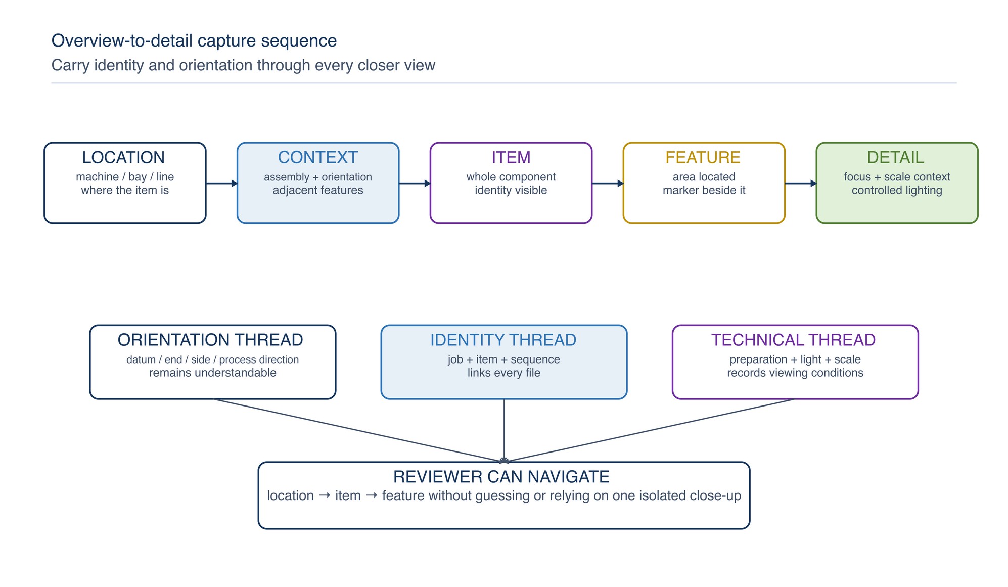
A complete image set normally moves from where the item is to what the feature looks like. [S267; S274]
| View | What it establishes | Typical content |
|---|---|---|
| Location | Where the condition exists | Machine, bay, line, structure or installation area |
| Context | How the item sits within the assembly | Adjacent components, access, orientation and process direction |
| Item | Which component is being discussed | Whole part, item ID, drawing reference or unique geometry |
| Feature | Where the relevant area lies on the item | Pointer beside the feature, weld segment, edge or surface zone |
| Close detail | What the feature looks like | Texture, indication, damage, deposit, finish or marking |
| Alternate-light view | How appearance changes with controlled illumination | Low-angle, diffuse, cross-light or backlit view |
| Post-action repeat | What changed after authorised work | Same orientation, scale, lighting and framing where practical |
Do not begin and end with a macro image. A reviewer should be able to travel from the location view to the close detail without guessing.
Identify the item and orientation
Use an identification card, job number, part label, drawing reference or other controlled identifier that can be linked to the report. Position it beside the item, not over the feature. Avoid including customer-sensitive information beyond what the report needs.
Record orientation with plain terms that fit the item: drive end, operator side, top, inlet, outlet, clockwise direction, weld start, datum face or another unambiguous reference. If a removable arrow or marker is used, photograph one view without it when the marker could hide surface condition.
Number and describe photographs carefully. A useful caption identifies the item, view, location of the feature, capture condition and purpose. [S274]
Choose field of view and working distance
Fill enough of the frame with the subject to preserve detail, but retain the context needed for interpretation. Moving extremely close with a wide-angle phone lens can exaggerate near features, curve straight edges and change apparent proportions. When space allows, step back and use an appropriate focal length or optical magnification.
Select working distance so that:
- the camera can be held or mounted safely;
- the feature fills the intended part of the frame;
- the lens can focus reliably;
- lighting can reach the surface without blocking the camera;
- perspective is controlled; and
- the camera, scale and hands do not touch the feature.
Digital zoom usually crops and enlarges the existing pixels. It may help framing on screen but does not create missing detail. Capture the highest useful native quality available and confirm the feature is resolved in the saved file, not only in the live preview. [S267]
Stabilise before increasing magnification
Close photography amplifies small movements. Use a tripod, copy stand, rigid arm, beanbag, stable platform or another suitable support where practical. Prevent the support from becoming a trip hazard or contacting moving, hot or energised equipment.
For handheld capture:
- brace elbows or the camera against a stable safe surface;
- use two hands;
- avoid reaching at full extension;
- use a short timer or remote release when pressing the shutter causes movement;
- take more than one frame; and
- review at high magnification for motion blur.
Adding light can support a faster exposure and reduce motion blur. Raising electronic sensitivity may make capture easier but can add noise and reduce fine detail. Select settings according to the inspection purpose rather than a universal formula.
Control focus and depth of field
Place focus on the feature of interest, not on a bright reflection, scale edge or nearby label. At close distance, only a shallow depth may appear sharp. A curved surface, deep gouge or raised weld may therefore require:
- a more square camera position;
- a smaller aperture where the camera permits and sufficient light is available;
- greater working distance with suitable focal length;
- separate frames focused at different depths; or
- a controlled optical system designed for extended-depth imaging.
Do not rely on the small screen. Enlarge the saved image and inspect the relevant edges and texture. If software combines multiple focus planes, keep the source images and identify the combined result as processed.
Select lighting by feature, not convenience
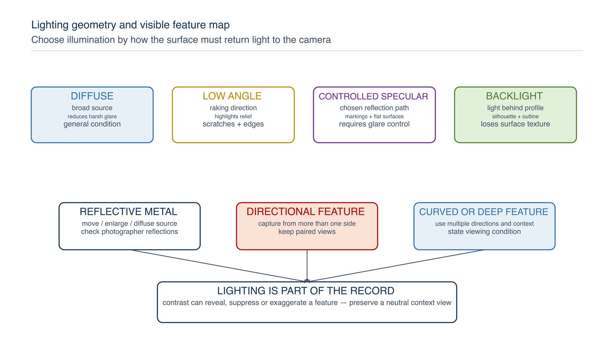
Lighting determines which surface information becomes visible. The same scratch can disappear under broad frontal light and become prominent under low-angle light. Specular, diffuse and transmitted arrangements are useful starting points, and the best direction depends on surface shape and inspection purpose. [S270]
| Inspection purpose | Useful starting light | Watch for |
|---|---|---|
| General surface condition | Broad diffuse light from above or beside the camera | Flat contrast that hides shallow texture |
| Fine scratches and raised edges | Low-angle light across the surface | Directional shadows that exaggerate height |
| Reflective flat metal | Large diffuse source or controlled off-axis light | Hot spots, reflected people and dark camera silhouette |
| Engraving, stamping or shallow relief | Oblique light from one or more directions | A single direction hiding features aligned with the light |
| Through-hole, profile or edge shape | Backlight where safe and physically possible | Silhouette loses surface information |
| Contamination or colour variation | Stable neutral illumination with controlled white balance | Mixed daylight and artificial light changing colour appearance |
| Deep recess | Small directed light supplemented by a context view | Bright rim with an unreadable dark interior |
| Curved polished surface | Diffuse enclosure, flags or cross-polarisation where suitable for defects | Uneven brightness and reflections being mistaken |
Move the light, not the safety boundary. Take paired views under different controlled directions when a feature is directional. Record unusual lighting arrangements so a repeat image can be made.
Manage glare and reflections deliberately
Polished metal acts like a mirror. A bright patch may be the lamp, and a dark patch may be the camera or photographer.
Change one variable at a time:
- move the light farther off axis;
- enlarge or diffuse the source;
- change the camera angle slightly while preserving the required geometry;
- use white or black cards outside the frame to control reflected surroundings;
- use a polarising arrangement where it is effective and does not suppress relevant evidence; and
- capture a second angle to show whether a mark follows the surface or the reflection.
Do not retouch reflections out of a released inspection image. If an alternate-light view improves visibility, keep both the neutral context view and the feature-enhancing view.
Use scale references correctly
A scale gives size context only when its geometry and quality are suitable. Place a clean, legible scale close to the feature and in the same plane where practical. Keep it parallel to the surface direction being compared and avoid covering the indication. Capture a view without the scale if placement could disturb or obscure the condition. [S267; S268]
| Scale-control question | Good practice | Limitation to state or manage |
|---|---|---|
| Is the scale suitable? | Use a stable, legible reference with appropriate graduations and known identity | Printed or worn scales may not have verified dimensional quality |
| Is it in the feature plane? | Place it at the same depth and orientation as the nominally flat feature | A different plane creates perspective error |
| Is the camera square? | Keep the optical axis as perpendicular as practical for flat features | Oblique capture changes apparent length and shape |
| Is distortion controlled? | Avoid extreme close-range wide-angle views; keep the feature near the central field | Lens distortion varies across the frame |
| Is the scale readable? | Preserve the complete relevant graduations and unit comparison | A cropped or blurred scale cannot support reliable comparison |
| Is measurement intended? | Use a validated calibrated imaging or photogrammetry method | An ordinary image with a ruler is not automatically a dimensional result |
When a photograph is used to indicate a measurement location, record the actual value from the controlled measuring instrument separately. Refer to the product label, Technical Data Sheet, or MKTECH representative.
Control perspective and shape
For nominally flat features, position the image sensor as parallel to the feature plane as practical. Use visible parallel edges or a small level aid where safe. Keep the area of interest near the centre of the frame and capture an oblique context view separately if it helps show depth.
For curved surfaces, no single view represents all points without distortion. Use multiple overlapping views and state the orientation. A scale laid across a curve may not share the same plane as the entire feature. If profile, flatness, angle or area is decision-critical, use the applicable controlled measurement method.
Perspective can also change apparent abrasive contact angle, guard clearance, weld shape and scratch length. Avoid making geometric claims from an uncontrolled viewpoint.
Treat colour as conditional information
Colour in a photograph depends on the light spectrum, reflections, exposure, white balance, camera processing, file profile, display and viewing environment. International camera colour characterisation uses controlled stimuli and metrology; an ordinary workshop photograph does not provide that control. [S266]
For colour-sensitive documentation:
- avoid mixed light sources;
- use a stable, suitable neutral light;
- set and record a repeatable white-balance method;
- include a suitable neutral or colour reference when the workflow calls for one;
- avoid clipping bright channels on reflective surfaces;
- preserve the original file and colour profile;
- compare images on a controlled display where the decision warrants it; and
- confirm critical colour or appearance using the applicable instrument or agreed visual method.
Heat tint, coating shade and contamination may be documented photographically, but image colour alone should not be converted into temperature, oxide thickness, chemical identity or acceptance unless a validated method supports that conclusion.
Use a repeatable capture record
Record enough information to recreate an important view. The level of detail should match the consequence and comparison need.
| Record field | Why it matters | Example content |
|---|---|---|
| Job and item ID | Connects image to report and component | Work order, part ID, batch or location |
| Photographer and date/time | Establishes capture responsibility and sequence | Name or controlled user ID plus timestamp |
| View and orientation | Allows the feature to be relocated | Operator side, inlet end, weld clock position |
| Camera and lens mode | Supports repeat setup and file interpretation | Device ID, lens or magnification mode |
| Working distance and support | Controls framing, perspective and stability | Marked stand position or approximate distance |
| Lighting arrangement | Explains contrast and reflection | Diffuse overhead, low-angle from left, backlight |
| Scale or reference ID | Links the visible reference to its control | Reference identity and unit |
| Preparation state | Distinguishes as-found, cleaned and post-repair views | Dry as found, solvent cleaned, after dressing |
| Original filename | Preserves traceability to the native file | Camera filename retained in the image register |
| Processing history | Identifies crops, exposure changes, composites or annotations | Working copy only; original preserved |
Where exact device capability, operating condition or approved accessory is required, use the applicable controlled information for that device.
Preserve originals and control working copies
Transfer files promptly to the controlled project location. Preserve the original image in its native captured form, including available metadata. Perform cropping, tonal adjustment, redaction, arrows, labels and other processing on a copy. [S269]
A practical file relationship is:
- JOB-ITEM-VIEW-SEQUENCE_ORIGINAL.ext
- JOB-ITEM-VIEW-SEQUENCE_WORKING-v01.ext
- JOB-ITEM-VIEW-SEQUENCE_ANNOTATED-v01.ext
Do not overwrite the original with an annotated version. Keep processing proportionate and reversible where practical. Adjustments may improve visibility but must not add, remove or relocate a feature. Record material processing, especially stitching, focus stacking, noise reduction, perspective correction or generative editing. Do not use generative fill or content-aware replacement on technical inspection content.
Verify the transferred file opens correctly, retains sufficient detail and matches the item and sequence record before clearing removable media.
Annotate without changing meaning
Annotations should direct attention, not create a conclusion. Use an arrow, circle, box or short label on a controlled copy and keep it outside the feature where possible. State whether the annotation identifies a location, an observed indication or an accepted defect classification.
Avoid:
- drawing over the feature boundary;
- using a thick arrow that suggests a size;
- increasing contrast until texture disappears;
- presenting a cropped image without its linked context view;
- removing background items that affect interpretation;
- placing an unverified dimension on the image; or
- using colour-coded pass/fail labels without the applicable decision record.
Captions should distinguish observation from interpretation. “Linear dark indication at the 3 o’clock edge” is an observation; “crack caused by grinding” is a technical conclusion that needs supporting inspection and analysis.
Repeat photographs for comparison
A before-and-after pair is useful only if changes in imaging are controlled. Match, as practical:
- item orientation and camera viewpoint;
- working distance and focal length;
- field of view and crop;
- focus plane and depth of field;
- light position, size, direction and colour;
- scale position and identity;
- surface preparation state; and
- exposure and colour workflow.
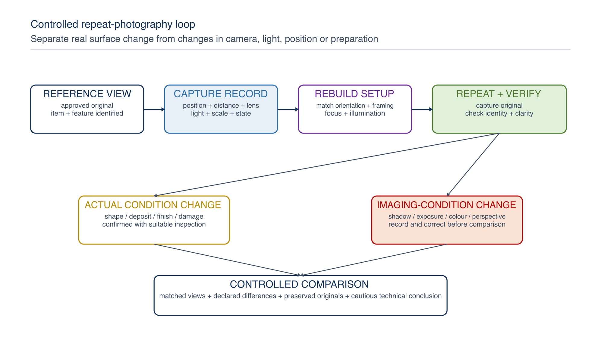
When an exact match is impossible, record the difference. Do not attribute a darker image, stronger highlight or changed shadow automatically to surface deterioration or improvement.
Troubleshoot the image before release
| Symptom | Likely cause | Practical correction |
|---|---|---|
| Feature is sharp on screen but soft in the file | Camera movement, wrong focus target or insufficient depth of field | Stabilise, refocus on the feature, add light and review at full size |
| Bright patch hides the surface | Direct specular reflection | Move or diffuse the light, alter view slightly and capture an alternate-light pair |
| Fine scratch disappears | Light aligned poorly with the scratch or contrast is too flat | Apply low-angle light across the feature from more than one direction |
| Surface looks rougher than it is | Strong raking light exaggerates relief | Add a diffuse context view and label the raking-light view |
| Scale looks readable but feature size is inconsistent | Scale and feature are in different planes or camera is oblique | Reposition scale, square the camera and avoid dimensional conclusions from the image |
| Colour changes between frames | Mixed lighting, auto white balance or exposure shift colour | Use one stable source and a controlled repeatable colour workflow |
| Close-up cannot be located | Context and orientation views are absent | Add linked location, item and feature views |
| Repeated view does not match | Position, focal length, light or preparation changed | Rebuild from the capture record and document unavoidable differences |
| Annotation hides the indication | Mark-up applied over technical content | Return to the original and annotate a clean copy outside the feature |
| Image cannot be traced to the job | Filename, item ID or sequence record is incomplete | Reconcile before release; do not rely on memory |
If a feature remains ambiguous, change the lighting or use the appropriate inspection method. Repeatedly sharpening or enlarging a weak file cannot recover detail that was never captured.
Inspection-photography release checklist
Before including an image in a customer report, technical recommendation or handbook asset, confirm:
- [ ] photography was authorised and performed from a safe position;
- [ ] the device was permitted for the area and conditions;
- [ ] the as-found state was preserved or the preparation state is clear;
- [ ] the image set includes enough location, context, item and detail views;
- [ ] item identity and orientation are unambiguous;
- [ ] the feature is in focus and resolved in the saved file;
- [ ] lighting reveals the intended feature without an unrecognised reflection;
- [ ] any scale is clean, legible, suitably placed and not overstated as calibrated measurement;
- [ ] colour language reflects the limits of the capture workflow;
- [ ] the original file and metadata are preserved;
- [ ] processing and annotation were performed on controlled copies;
- [ ] captions distinguish observation from interpretation;
- [ ] repeat images control or declare changed conditions;
- [ ] confidential, personal and customer-sensitive content is handled appropriately; and
- [ ] the released image is linked to the correct report, item and sequence record.
Abrasive Safety Fundamentals
The Abrasive Safety Fundamentals chapter begins on the following page of the printed handbook (page 397), outside this chapter extract.