
Production managers, engineers, supervisors, operators, maintenance personnel, QA/QC teams, planners and continuous-improvement teams
Labour per accepted component; work observation; quality at source; standard work; workplace organisation; ergonomics; equipment readiness; setup and changeover; defect containment; root-cause improvement; verification and sustainment.
Labour reduction never justifies bypassing a guard, inspection, extraction, isolation, secure mounting, workholding or PPE requirement. Confirm product and machine compatibility, marked limits, accessory condition and operator authorisation. Stop for abnormal vibration, damage, unexpected heat, loss of secure mounting, unstable work or any condition outside the approved method.
The best labour reduction removes work that does not create an accepted result. It must preserve safe operation, product conformity, traceability and operator control.
Grinding and surface finishing often contain hidden labour: searching for the correct product, moving parts repeatedly, correcting unstable workholding, waiting for inspection, changing abrasives prematurely, repeating passes and repairing defects detected late. Rework consumes labour and abrasive while adding no accepted output. A stable process prevents the defect or detects it close to the point where it was created.
When an exact product value is required, Refer to the product label, Technical Data Sheet, or MKTECH representative.
Chapter objectives
After this chapter, the reader should be able to:
- measure labour and rework against accepted output;
- distinguish processing work from avoidable motion, waiting and correction;
- define a clear incoming condition and accepted handoff;
- build practical standard work for abrasive operations;
- organise products, accessories, gauges and documents at point of use;
- improve work positioning and handling;
- reduce setup and product-change losses;
- contain abnormal output and diagnose the originating cause;
- use balanced indicators that discourage shortcuts; and
- verify improvements under representative production conditions.
Measure labour against accepted output
Use a denominator that reflects usable production:
Direct labour per accepted unit = direct labour time within the defined process boundary ÷ final accepted units
Record rework labour separately. Include time spent correcting components that failed the first applicable acceptance check, even if the correction occurs at another workstation or shift. For mixed work, normalise by an agreed unit such as accepted cut length, weld length or finished area, and keep the product family and difficulty visible.
Do not report a labour improvement from fewer inspection, extraction, guarding, handling or quality-control activities unless those activities are genuinely unnecessary and their removal has been approved through the workplace change process.
Define the process boundary
State where measurement begins and ends. A useful boundary may begin with a released workpiece and available job information, and end with accepted output handed to the next operation. Include:
- job identification and drawing review;
- product, accessory and machine preparation;
- workholding and part positioning;
- abrasive processing;
- in-process and final checks;
- product changes and normal cleanup;
- internal movement and waiting; and
- correction, repeat inspection and disposition.
Consistent boundaries prevent apparent improvement created by moving work to another person or department.
Make labour loss visible
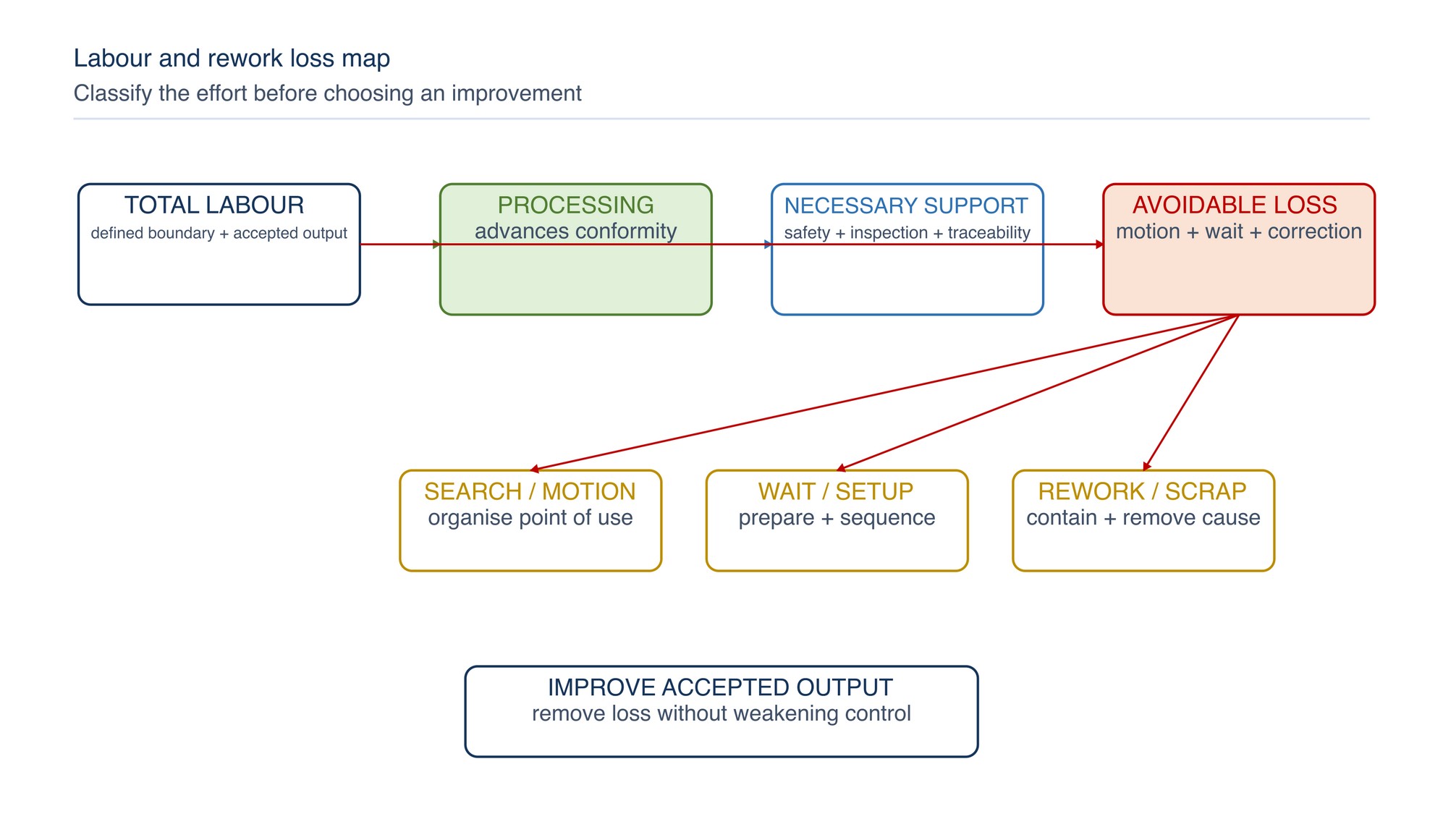
| Work category | Typical example | Improvement direction |
|---|---|---|
| Value-creating processing | Controlled stock removal or finishing that advances conformity | Stabilise and optimise |
| Necessary support | Inspection, safe mounting, extraction check or traceability | Make reliable and efficient |
| Search and motion | Looking for discs, gauges, drawings or fixtures | Point-of-use organisation |
| Waiting | Machine, material, approval or inspection unavailable | Readiness and flow control |
| Repeated setup | Re-clamping, re-zeroing or repeated masking | Setup standard and preparation |
| Over-processing | Unnecessary passes or finish finer than required | Clarify acceptance and sequence |
| Rework | Correction after a failed check | Contain and remove root cause |
| Scrap handling | Processing and disposition of unusable work | Prevent recurrence and record cause |
Observe the work at the workstation with operators. A time record without the reason for each delay cannot distinguish skill, difficulty, equipment condition and system loss.
Define accepted input and handoff
The operator needs a clear answer to two questions: what condition may enter this operation, and what condition may leave it? Define applicable requirements for:
- material and component identity;
- weld, edge, coating or previous-operation condition;
- permitted contamination and damage;
- dimensional or geometric boundaries;
- surface finish or visual comparator;
- protected features and no-touch areas;
- cleaning and inspection status; and
- traceability and route documentation.
Ambiguous acceptance encourages either unnecessary finishing or defects passed downstream. Use controlled drawings, specifications, approved samples or visual standards appropriate to the work.
Build quality at the source
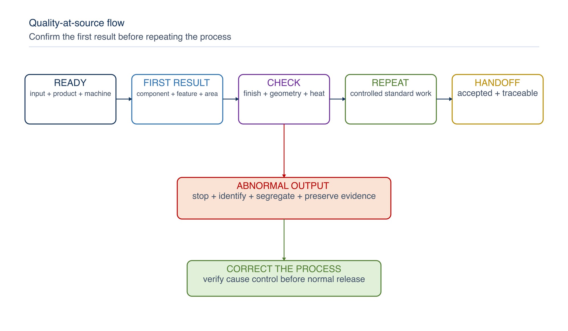
Check the first component, first feature or first representative area after setup and after a significant change. Select a check point early enough to prevent a full batch from inheriting the same defect. The check may cover:
- required material removal;
- burr or edge condition;
- surface texture or visual appearance;
- dimensional and geometric preservation;
- heat tint, burning or thermal damage indicators;
- scratch direction and transition quality;
- cleanliness and cross-contamination; and
- downstream fit, coating or polishing requirement.
If output is abnormal, stop the affected sequence, identify potentially affected work and investigate before continuing. Re-inspection alone does not remove the cause.
Standardise the complete operation
Standard work is the agreed current method for producing a safe, conforming result with available people and equipment. It should be concise, visible and updated after approved improvement. NIST manufacturing guidance connects standard work with reduced variation, mistakes, rework and scrap. [S384; S385]
Cover:
- component and operation identity;
- abrasive and accessory identity;
- pre-use inspection and compatibility checks;
- workholding, protection and presentation;
- safe sequence and processing stages;
- contact, travel and overlap method;
- in-process inspection point;
- observable change-out condition;
- cleaning and material-separation controls;
- abnormal-condition response; and
- accepted handoff.
Do not encode an assumed universal speed, force, angle or service life. The method must follow the exact product, machine and application information.
Organise the point of use
Place frequently used items where they can be reached, identified and returned without confusion. Use controlled locations for:
- released abrasive products by full identity;
- backing pads, contact elements, flanges and adaptors;
- guards, keys and permitted mounting tools;
- fixtures, clamps and protection materials;
- inspection equipment and visual standards;
- cleaning tools and material-specific equipment;
- current work instructions; and
- usable partial products and rejected items.
Visual labels should distinguish status, not merely location. Remove obsolete documents and segregate damaged or unidentified abrasives. NIST identifies workplace organisation and point-of-use control as foundations for reducing search, motion and error. [S383; S384]
Prepare a job kit
For repeated or planned work, assemble the authorised products, accessories, gauges, fixtures and documents before the machine becomes unavailable for changeover. Confirm quantity and condition without issuing uncontrolled excess stock.
A job kit can reduce walking and interruption, but it must preserve product identification, storage protection and return status. Similar-looking grades should not be placed together without unmistakable identification.
Improve work positioning
Position the work so the operator can maintain control with neutral joints, good visibility and supported handling. Consider:
- working height and orientation;
- distance and reach to the contact zone;
- wrist alignment and handle orientation;
- elbow position and body balance;
- fixture access and part rotation;
- cable, hose and extraction routing;
- lifting, turning and transfer method; and
- planned recovery and task rotation where appropriate.
OSHA ergonomic guidance identifies repetitive motion, forceful exertion and awkward posture as risk factors and recommends repositioning work and maintaining more neutral upper-limb posture. [S386] Ergonomic improvement must not bring the operator into the line of fire, obstruct a guard or reduce secure workholding.
Support the tool and workpiece
Tool balancers, stands, positioners, manipulators, turntables and purpose-designed fixtures may reduce handling effort where they are suitable for the machine, product and workpiece. A fixture should:
- locate the part consistently;
- resist process forces and vibration;
- provide safe access to required surfaces;
- avoid damaging finished or datum surfaces;
- permit inspection and controlled release;
- avoid pinch, entanglement and ejection hazards; and
- remain compatible with guarding and extraction.
Treat any new support or fixture as a machinery or process change requiring risk review. ISO 12100 provides the recognised framework for hazard identification and risk reduction. [S358]
Confirm equipment readiness
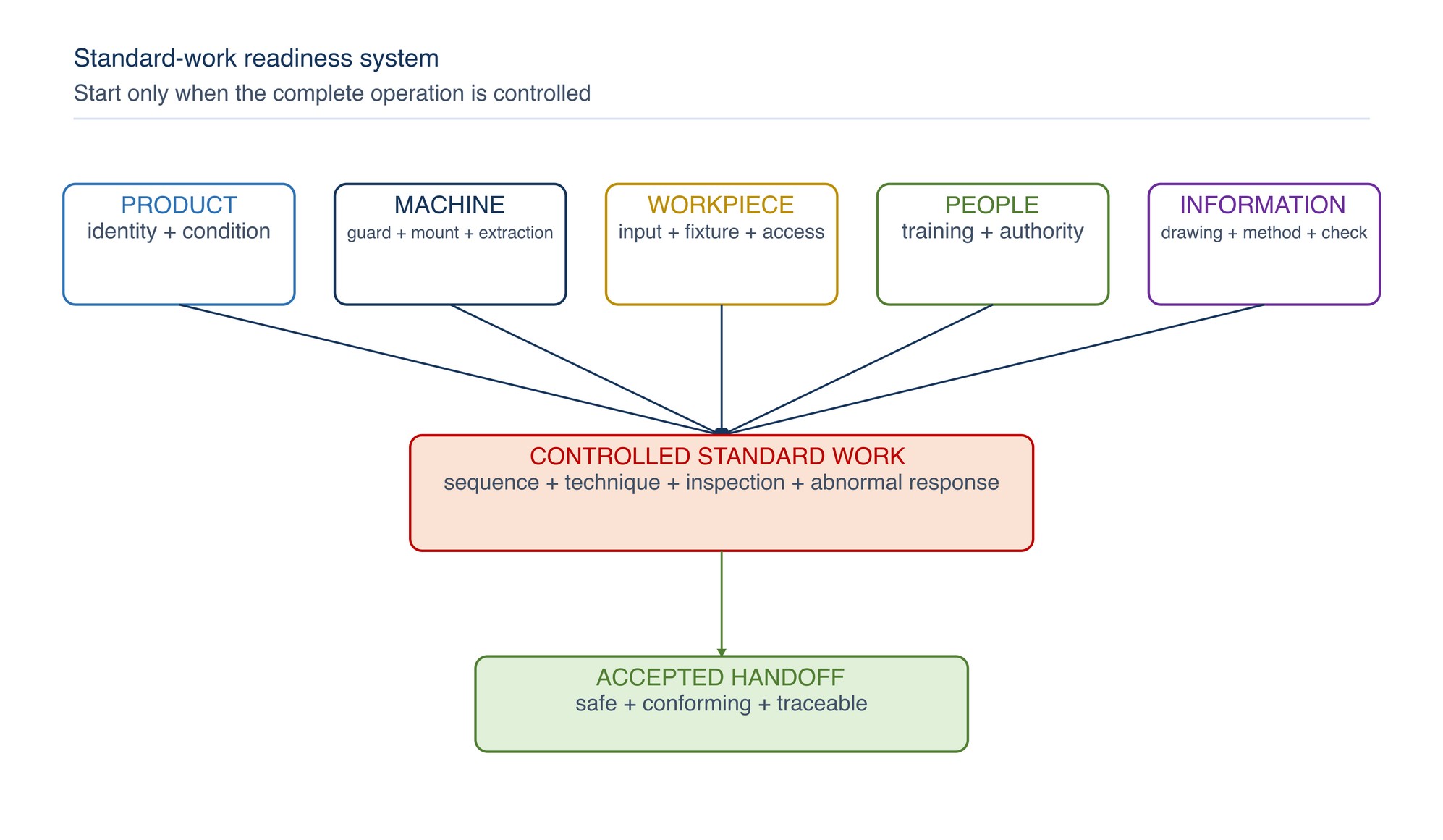
Before the job starts, confirm:
- correct machine and power source;
- guard, mounting and controls in serviceable condition;
- spindle, bearings, drive and speed control normal;
- extraction and ventilation available;
- correct abrasive and support accessory;
- secure workholding and access;
- calibrated or otherwise controlled measuring equipment where required;
- current drawing, route and work instruction; and
- trained, authorised personnel.
Breakdowns, runout, poor extraction and worn support equipment cause repeat passes and defects. A faster abrasive cannot correct an unready system.
Reduce setup and changeover loss
Separate activities into those that require the equipment to be stopped and those that can be completed safely while the preceding job is running. External preparation can include confirming the next job, staging released products, checking gauges, cleaning fixtures off-line and reviewing the drawing.
During the stopped period, use a defined sequence for isolation where required, removal, cleaning, inspection, mounting, guarding, adjustment, first-result check and release. NIST describes quick changeover from the last good piece of one run to the first good piece of the next, keeping quality central to the definition. [S383]
Never pre-loosen a mounting, bypass isolation or leave a machine unguarded to save changeover time.
Reduce unnecessary product changes
Product changes consume labour and can introduce mounting error. Reduce avoidable changes by:
- selecting the correct abrasive for the complete operation;
- using a logical grit or stage progression;
- maintaining the support accessory and machine;
- applying a common condition-based change rule;
- preventing loading, contamination and localised wear;
- organising the sequence to minimise incompatible material changes; and
- protecting identified partial products for permitted reuse.
Do not extend a product beyond its designed working area, safe condition or marked limit. A change avoided through unsafe overuse is not an improvement.
Remove unnecessary stages carefully
A stage may be unnecessary when it does not change the component toward a stated requirement and does not protect safety or downstream quality. Examples include repeating a grit because the previous stage is poorly controlled, polishing a hidden surface beyond the drawing requirement or inspecting the same feature multiple times because status is unclear.
Before removing a stage, confirm its original purpose, upstream and downstream effects, defect-detection role and process risk. Verify the revised sequence on representative work. Do not remove cleaning, edge treatment, inspection or traceability merely because its benefit is not immediately visible.
Classify rework by the observed defect
| Rework family | Typical process causes to check | Immediate control |
|---|---|---|
| Deep scratch or stray mark | Contamination, wrong sequence, handling, loose particle, uncontrolled contact | Protect and segregate affected work |
| Heat tint, burn or distortion | Dwell, excessive force, dull product, poor contact, inadequate cooling | Stop processing and inspect extent |
| Burr remains or returns | Incomplete access, inconsistent presentation, unsuitable stage, damaged edge | Identify affected features and method |
| Geometry changed | Excess removal, dwell, unsupported edge, poor fixture or measurement | Hold work and verify dimensions |
| Uneven finish | Variable overlap, worn support, inconsistent pressure, local loading | Contain visual or measured variation |
| Embedded contamination | Shared tools, unsuitable abrasive, dirty handling or mixed work area | Segregate material and clean system |
| Missed area | Poor visibility, route ambiguity, fixture obstruction or handoff error | Mark and control feature coverage |
| Coating failure after finishing | Residue, surface profile, cleaning or environmental condition | Hold downstream work and trace preparation |
Record the defect where it is found and where it was most likely created. The detecting process and originating process may be different.
Contain abnormal output
When a defect is detected:
- Stop further processing when continuation could create more affected work or increase risk.
- Identify the last known conforming condition.
- Segregate work produced since that point.
- Preserve product, machine, accessory and setting identity.
- Assess the defect using the approved acceptance method.
- Decide correction, concession, scrap or other disposition through authorised quality control.
- Correct the process cause before normal release.
Do not blend out a defect automatically. Additional material removal may affect dimensions, fatigue-sensitive geometry, coating preparation or visual consistency.
Find the originating cause
Investigate across the complete system:
- specification and incoming condition;
- abrasive identity, condition and storage;
- machine and support accessory;
- workholding and access;
- method, sequence and change-out rule;
- inspection method and equipment;
- environment, extraction and contamination control; and
- training, workload and communication.
Use repeated observations and physical evidence. A defect concentrated on one edge may point to presentation or support; a defect across operators may point to selection, equipment or instruction. Avoid assigning blame before checking the system.
Use error prevention and visual control
Simple controls can prevent repeat work:
- keyed or clearly identified fixtures;
- protected no-touch zones;
- templates for coverage or transition boundaries;
- shadow boards and labelled storage;
- separate colour or status locations for material families;
- approved finish samples under controlled lighting;
- first-piece release markers; and
- route cards that expose incomplete features.
Visual controls must remain understandable, durable and revision-controlled. Colour alone should not be the only distinction where misidentification creates risk.
Verify the improvement
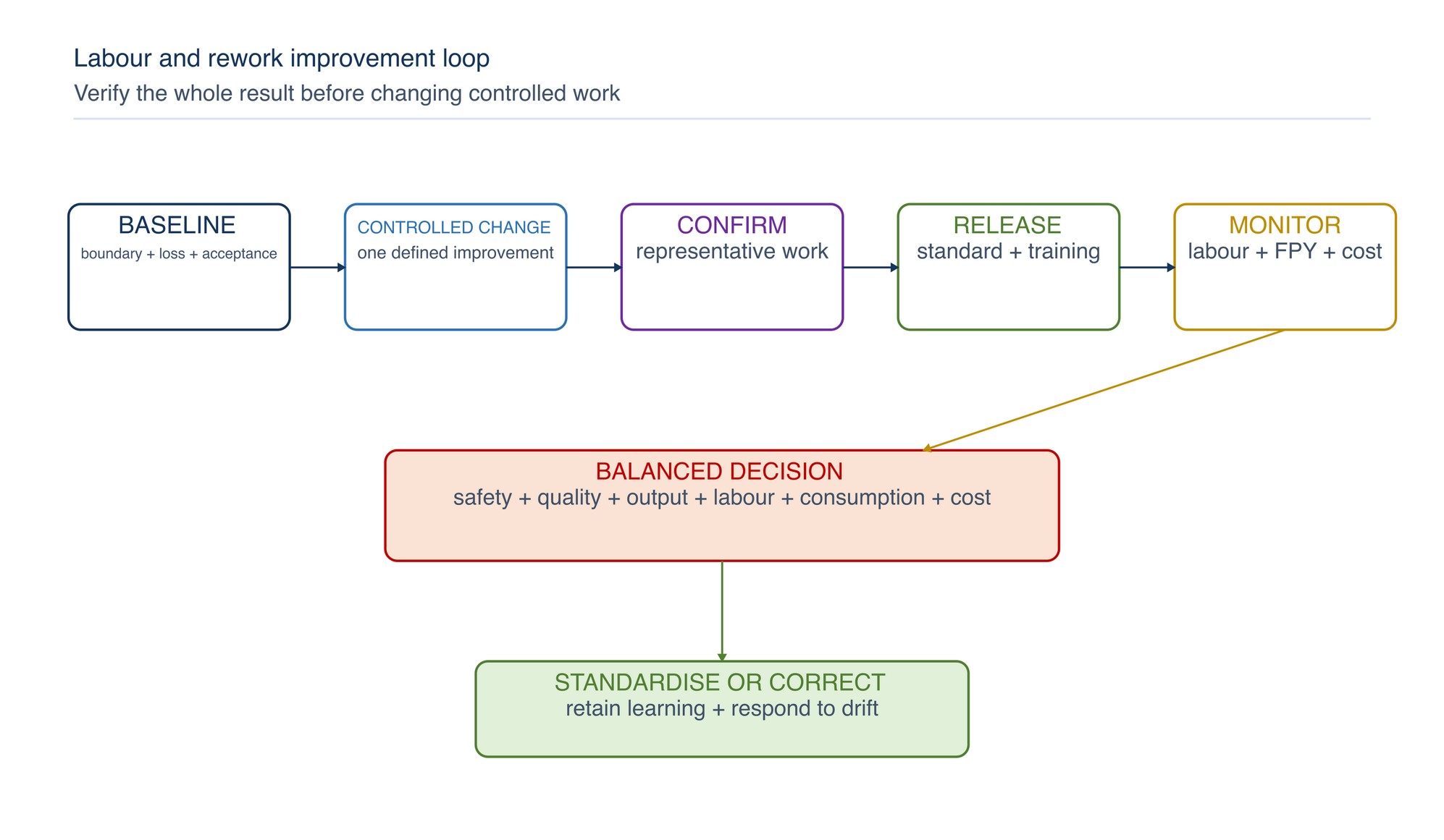
Compare baseline and proposed method using the same process boundary, workpiece population, acceptance method and labour definition. Track:
- labour per accepted unit;
- first-pass yield;
- rework labour and components affected;
- scrap and concession status;
- setup and product-change time;
- waiting and search time;
- abrasive consumption;
- safety or abnormal events; and
- cost per accepted component.
First-pass yield describes output meeting quality requirements without scrap, rerun, retest, return or off-line repair. [S372] Use Chapter 063 for controlled comparisons and Chapter 062 for cost per accepted component. Confirm the result across representative operators, workpiece conditions and production periods before revising controlled work.
Sustain the result
| Indicator | What it reveals | Review trigger |
|---|---|---|
| Labour per accepted unit | Complete processing effort | Sustained movement from baseline |
| First-pass yield | Prevention effectiveness | Decline by product, job or shift |
| Rework labour | Hidden correction burden | Repeat defect family or rising hours |
| Setup/changeover time | Readiness and sequence loss | Variation or recurring wait |
| Search/wait time | Point-of-use and planning weakness | Repeat location, item or approval delay |
| Abrasive changes per accepted unit | Selection, use or condition loss | Change without output benefit |
| Cost per accepted component | Overall economic result | Labour reduction with higher total cost |
Review after changes to component design, material, product, machine, accessory, fixture, method, acceptance requirement, staffing or layout. Update the work standard and training after an approved change.
Practical labour-and-rework checklist
Confirm:
- the process boundary ends at accepted handoff;
- labour and rework are measured separately;
- incoming and outgoing conditions are clear;
- the first result is checked after setup or significant change;
- abrasive, accessory, fixture and inspection identities are controlled;
- products, tools, gauges and documents are organised at point of use;
- work height, reach, handling and visibility support control;
- machine, extraction and measurement systems are ready;
- internal and external changeover activities are distinguished;
- defects are contained and traced to the originating process;
- safety, quality, output and cost remain visible together; and
- approved improvements are incorporated into standard work.
Troubleshooting
| Problem | Likely cause | Improvement |
|---|---|---|
| Labour falls but defects rise | Acceptance or inspection weakened | Restore quality gate and verify method |
| Operators take very different times | Inputs, sequence or change-out rule vary | Observe work and standardise controllable elements |
| Rework appears late downstream | Early check does not cover critical feature | Move detection closer to source |
| Frequent searching interrupts work | Point-of-use locations or status unclear | Organise, label and replenish controlled locations |
| Product changes are frequent | Wrong selection, loading, damage or subjective rule | Diagnose condition and standardise change-out |
| Setup time varies widely | Preparation occurs after stoppage | Move safe preparatory work outside stopped period |
| Finish is inconsistent after breaks | Restart point or overlap is uncontrolled | Define restart and blending method |
| Operator force rises during task | Product dulling, support wear or machine issue | Stop and diagnose the complete contact system |
| Same defect returns after correction | Symptom repaired but cause unchanged | Preserve evidence and verify root-cause action |
| Fixture saves time but access is poor | Productivity change introduced new hazard or variation | Redesign and reassess risk before release |
Safety reminder
Labour reduction never justifies bypassing a guard, inspection, extraction, isolation, secure mounting, workholding or PPE requirement. Confirm product and machine compatibility, marked limits, accessory condition and operator authorisation.
Stop for abnormal vibration, damage, unexpected heat, loss of secure mounting, unstable work or any condition outside the approved method.
Key takeaways
- Measure labour against accepted output and expose rework separately.
- Define the process boundary so work is not merely transferred elsewhere.
- Prevent defects through clear handoffs, first-result checks and quality at source.
- Standardise product, support, workholding, sequence, inspection and abnormal response.
- Organise the workplace and prepare jobs before the machine stops.
- Improve posture, reach and handling while preserving safeguarding.
- Contain defects quickly and remove the originating cause.
- Verify labour reduction with safety, quality, output, consumption and total cost visible.
Factory Grinding and Finishing KPIs
The Factory Grinding and Finishing KPIs section appears on the following page of the printed handbook (page 602), outside this chapter extract.