
Cutting operators, supervisors, production engineers, maintenance personnel, QA/QC teams and technical buyers
Cut-off wheel integrity; guards and mounting; work support; kerf behaviour; binding and kickback; wheel breakage; slow cutting; stalling; cut deviation; burr and breakout; heat; wheel wear; interruption, re-entry and verification.
Use cutting wheels only on their designed cutting surface. Never twist, lever, side-grind, jam or force the wheel; never exceed a marked limit or operate without the correct guard and secure workholding. Stop for damage, vibration, binding, stall, work movement or loss of control. Allow the wheel to stop completely before inspection or removal.
A cutting wheel must remain on its designed cutting surface and in the intended cutting plane. If the work moves, the kerf closes or the wheel binds, stop and correct the physical cause.
Abrasive cutting problems are often system problems. Wheel damage, incorrect flanges, weak work support, a closing kerf, unstable guidance, machine power loss or unsuitable selection can produce the same symptom. Troubleshooting must begin with wheel integrity and control of the cut—not with additional force.
When an exact product value is required, Refer to the product label, Technical Data Sheet, or MKTECH representative.
Chapter objectives
After this chapter, the reader should be able to:
- identify cutting conditions that require immediate stop;
- confirm product, machine, guard and mounting compatibility;
- support work so the kerf remains controlled;
- recognise and prevent binding, pinch and kickback;
- diagnose slow cutting, stall, deviation, burr, heat and rapid wear;
- preserve evidence after wheel damage or breakage;
- interrupt and re-enter a cut only under the applicable machine instructions;
- distinguish hand-held and fixed-machine causes; and
- verify a correction against safety, cut quality, time and abrasive use.
Immediate stop conditions
Stop, isolate and inspect when there is:
- a cracked, chipped, warped, distorted or partly separated wheel;
- abnormal vibration, noise or contact with the guard;
- loose mounting, damaged flange or visible wheel movement;
- binding, pinching, kickback or uncontrolled tool movement;
- machine stall or repeated severe speed loss;
- workpiece movement or collapsing support;
- smoke, fire, unexpected heating or suspected combustible residue;
- loss of cut-line visibility or safe body position; or
- doubt about product identity, intended use or speed compatibility.
Do not pull a rotating wheel sideways from a cut. Maintain control, release the operating control as directed and allow complete stop before removal. Investigate the cause before restarting.
Confirm the complete identity
Check:
- cutting-wheel type and full product marking;
- intended material and operation;
- designed cutting surface;
- wheel dimensions and mounting interface;
- marked maximum speed relative to machine speed;
- machine type and capacity;
- correct cutting guard and handle;
- correct, clean, undamaged flanges and mounting parts;
- product condition and storage history; and
- current machine instructions and workplace method.
ISO 603-16 defines dimensional scope for common hand-held cutting-off wheel types, while ISO 11148-7 and IEC 62841-2-3 cover different non-electric and electric grinder safety contexts. [S088; S096; S280; S283] These standards do not establish an MKTECH product–machine pairing.
Use a cutting-problem diagnostic sequence
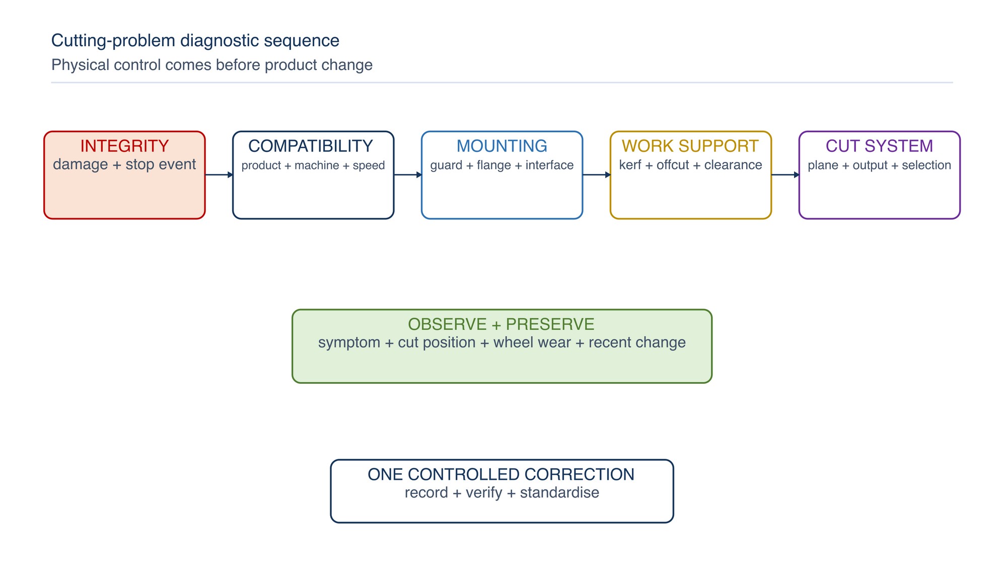
Check in order:
- wheel condition and stop event;
- product, machine and speed relationship;
- guard, flange and mounting condition;
- workpiece support and expected kerf movement;
- straight-plane entry, travel and exit;
- machine output, extraction or coolant where applicable; and
- wheel construction and application suitability.
Record the observed symptom, cut position and wheel wear pattern before disturbing the evidence.
Control work support and the kerf
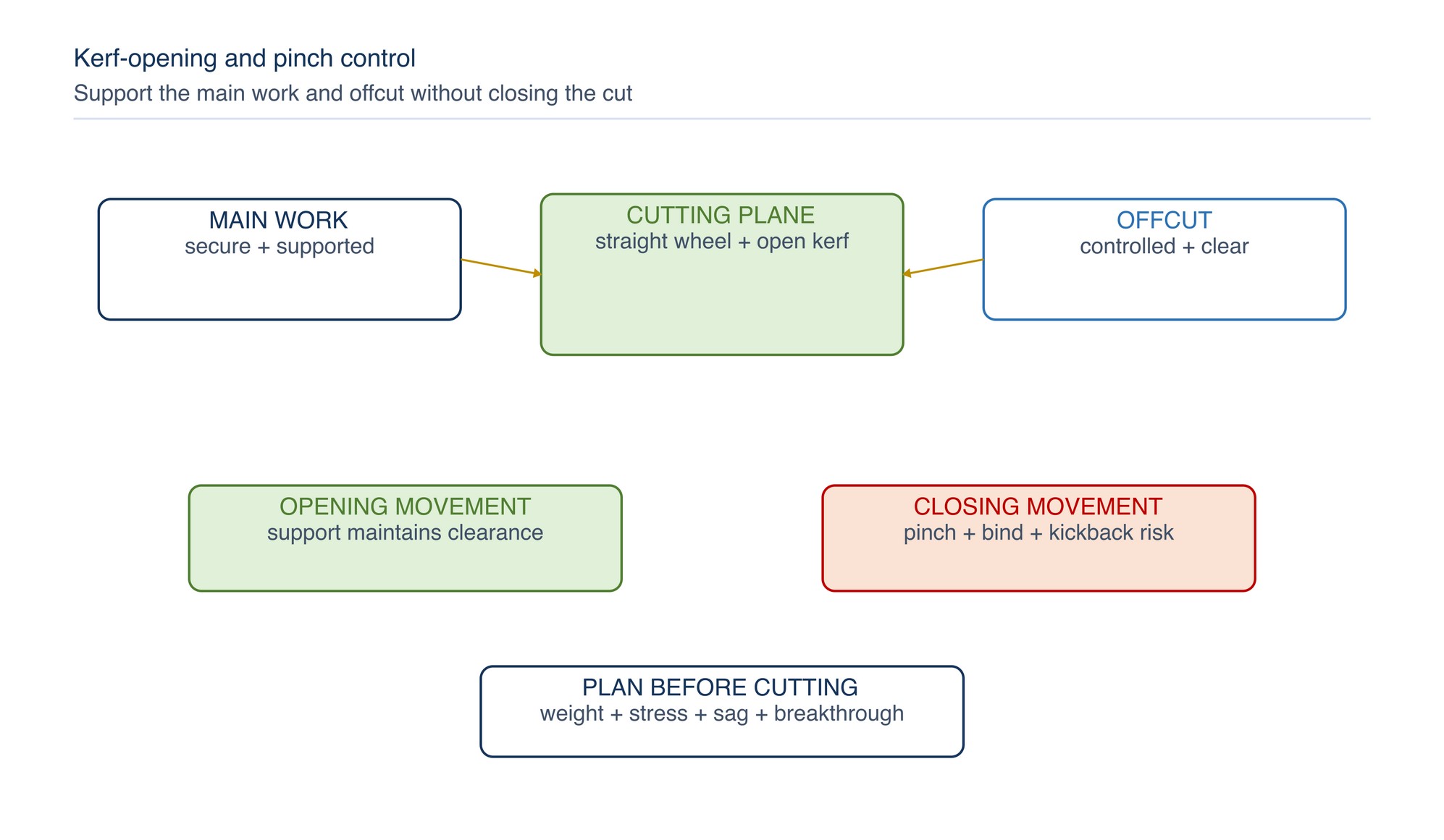
Plan how the work will move as material is removed. Consider self-weight, residual stress, curvature, section shape, temperature and offcut mass. Support should:
- prevent the main work from shifting;
- prevent the offcut from dropping unpredictably;
- keep the kerf from closing on the wheel;
- avoid excessive sag in sheet, plate, tube or profile;
- provide clearance for the wheel to complete the cut;
- avoid trapping the wheel at breakthrough; and
- retain safe access and line-of-fire control.
Work movement and wheel pinching are major cutting-wheel breakage mechanisms. [S392] The exact support arrangement depends on the component and must be assessed before cutting.
Binding, pinching and kickback
Binding occurs when the wheel is squeezed, deflected or obstructed in the cut. Kickback is a sudden reaction that can drive the tool or work unpredictably.
Common causes include:
- the kerf closing under weight or residual stress;
- offcut rotation or drop;
- tool twisting or cut-line correction while engaged;
- misaligned entry or re-entry;
- unsupported large sheet or profile;
- cut through a hidden object;
- wheel stalled by excessive feed;
- workpiece movement; and
- using a wheel or machine outside its intended capacity.
Stop after a bind. Inspect the wheel, mounting and work support. Do not resume with a wheel that may have been side-loaded or damaged.
Keep the wheel in the cutting plane
Cutting-off wheels are thin and designed to cut on the permitted periphery. They are not general side-grinding tools. Side pressure can damage reinforcement or overstress the wheel. [S393]
Avoid:
- twisting to steer the cut;
- levering the wheel to widen the kerf;
- grinding a burr with the wheel side;
- forcing a curved cut with a straight-cut product;
- entering at an uncontrolled angle;
- bumping the work at first contact; and
- allowing the work to push the wheel sideways at breakthrough.
If the cut is off line, stop safely and reassess. Do not bend the wheel back toward the mark while it is engaged.
Wheel breakage or major damage
After a breakage:
- stop and isolate the machine and work area;
- attend to people and immediate hazards under emergency procedure;
- prevent equipment restart;
- retain all wheel fragments, labels and packaging where safe;
- preserve flanges, adaptors and mounting arrangement;
- record machine, workpiece, cut position and operating observations;
- quarantine related products where indicated; and
- involve the responsible technical, safety and quality personnel.
Do not discard fragments or rebuild the arrangement merely to reproduce the event. Investigate all credible breakage causes, including overspeed, mounting, clamping, side force, machine condition, feed, coolant and product selection. [S392]
Slow cutting and excessive force
Check:
- wheel glazing or loading;
- incorrect wheel family for material or section;
- machine power, supply and speed-control condition;
- wheel used beyond efficient condition;
- excessive contact length;
- thick coating, scale or contamination;
- cut path obstructed by swarf;
- unstable work causing rubbing; and
- operator feed exceeding the wheel’s cutting response.
Do not compensate by leaning harder. Excessive force can heat, deflect or damage the wheel and can increase loss of control. HSE guidance favours cutting efficiency over nominal maximum wheel life. [S378]
Machine slows or stalls
A stall or severe speed drop may result from binding, excessive feed, inadequate power supply, worn drive components, incorrect machine capacity or a poorly cutting wheel. Stop and inspect before re-entry.
For pneumatic tools, check supply and hose condition under the machine instructions. For electric tools, check power source, controls and overload response. For fixed cut-off machines, check drive, spindle, slide and feed system. CCOHS advises against forcing a cut so that the motor slows. [S394]
Never restrain a stalled wheel in the kerf while attempting to restart.
Cut deviation, wandering and poor squareness
Possible causes include:
- wheel already distorted or damaged;
- side loading or steering pressure;
- flange contamination, mismatch or runout;
- spindle or pivot wear;
- workpiece movement;
- unequal support or sag;
- entry not aligned to the intended plane;
- feed applied unevenly; and
- wheel construction unsuitable for the section or required accuracy.
Check whether deviation begins at entry, develops through the section or appears only at breakthrough. The pattern helps separate alignment, support, machine and technique causes.
Excessive burr, breakout or rough edge
Review:
- wheel condition and suitability;
- cut direction and material support;
- feed stability near breakthrough;
- heat and material smearing;
- vibration or wheel deviation;
- section thickness and geometry;
- coating or scale condition; and
- downstream edge requirement.
A burr is not permission to use the cutting-wheel side for deburring. Complete edge treatment with a product designed and mounted for that operation.
Heat, discoloration and melting
Heat can arise from a glazing or loaded wheel, excessive force, long contact, slow cutting, poor chip clearance, unsuitable selection or inadequate wet-process control. On plastics, coated parts or low-melting materials, friction may smear or melt the edge.
Check the affected component against its quality requirements. Do not assume that a visually cleaned edge is free from thermal damage, hardness change, coating degradation or distortion. Keep fire and combustible-dust controls active throughout cutting.
Rapid wear, edge chipping and uneven wheel loss
Rapid or uneven wear may result from:
- side force or cut misalignment;
- workpiece pinch or movement;
- wheel impact at entry;
- excessive feed;
- unsuitable wheel construction;
- damaged or mismatched flanges;
- spindle or machine vibration;
- unequal coolant delivery on an approved wet process; and
- abrasive contact with an unintended surface.
Inspect the entire circumference and both faces only after isolation. Edge chipping is a damage signal, not a normal change-out cue to ignore.
Tube, bar and profile cutting
Hollow and shaped sections can change support as the cut progresses. Plan for:
- curvature or residual stress;
- collapse or rotation of thin-wall tube;
- offcut weight and fall direction;
- multiple wall entries and exits;
- pinching at the final ligament;
- internal contamination or coating; and
- sharp hot edges after separation.
Support the shape without crushing it and keep the offcut controlled. A warped section may move as the cut releases stress; use a competent job-specific support method.
Sheet, plate and large workpieces
Large work can sag under its own weight. Provide support near the cut and at free edges so that neither side closes onto the wheel or drops unexpectedly. Confirm that the cut will not release stored energy or destabilise the remaining structure.
For blind areas, walls, floors, tanks or used containers, identify hidden services, contents, residues and structural consequences before authorising work. Grinding or cutting can ignite flammable residues in used containers. [S323]
Interrupting and re-entering a cut
If cutting stops unexpectedly:
- keep the tool controlled until the wheel stops;
- remove it only without side loading;
- inspect the wheel and cut;
- correct binding, support or machine cause;
- restore a stable body and tool position; and
- re-enter only according to the exact machine instructions.
Manufacturer guidance commonly warns against restarting a hand-held cutting wheel while it remains in the work because it can bind, walk or kick back. [S097] Direction and re-entry sequence are machine-specific and are not universalised here.
Apply a controlled correction
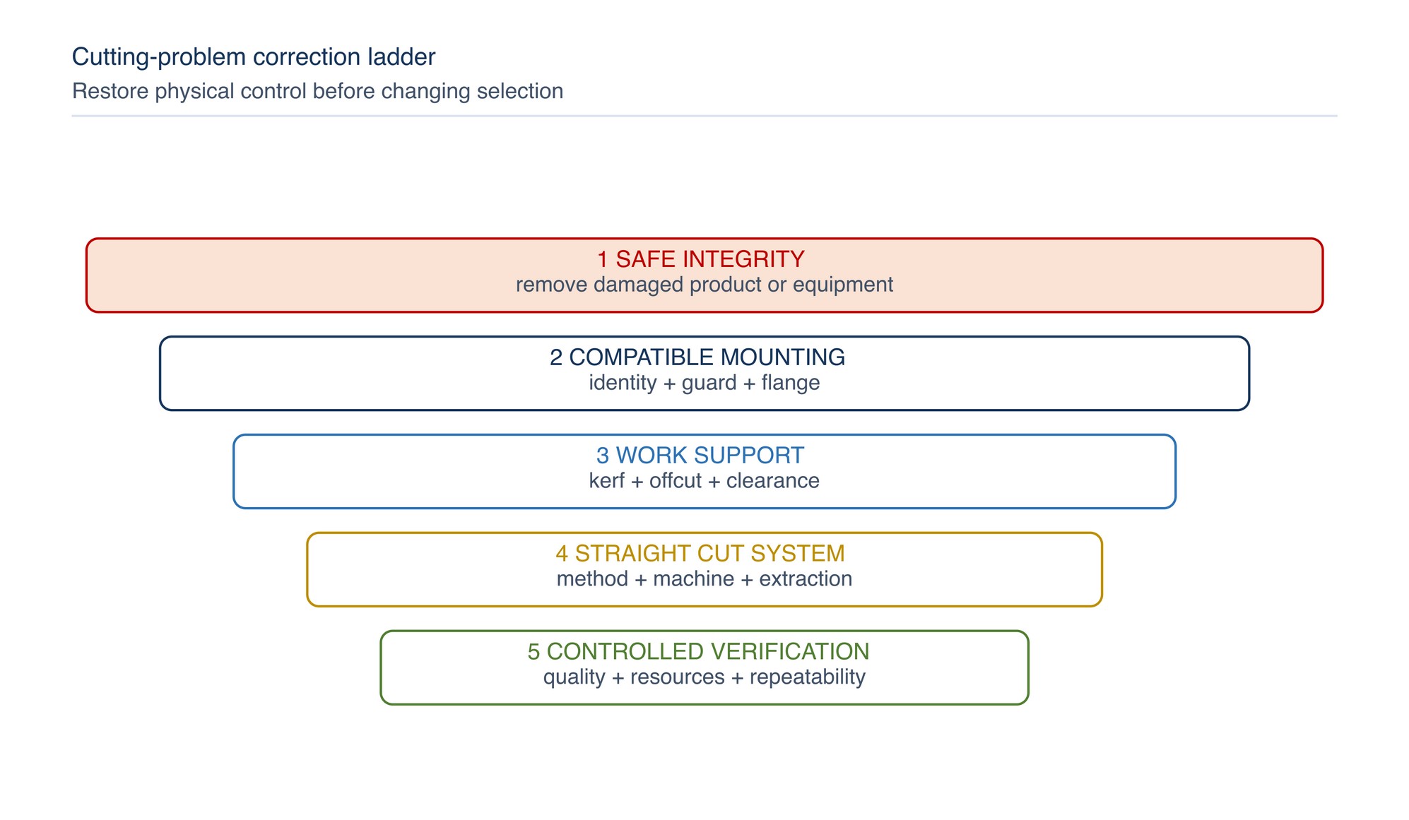
Use this order:
- remove damaged product or equipment from service;
- restore correct identity, guard, flange and mounting;
- correct work support and kerf behaviour;
- restore straight-plane entry, travel and exit;
- correct machine output, extraction or approved coolant system;
- review wheel construction and application suitability; and
- verify through a controlled comparison where a specification changes.
Change one controlled factor at a time whenever practical and record the result.
Verify and sustain
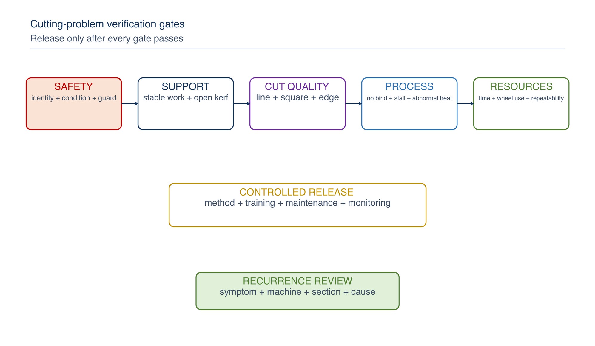
Confirm:
- product, machine, guard and mounting compatibility;
- stable workholding and open kerf behaviour;
- straight, controlled cutting without bind or stall;
- accepted cut location, squareness and edge condition;
- absence of unacceptable thermal or mechanical damage;
- task time and wheel use on an accepted-output basis;
- repeatability across representative work; and
- updated method, training or maintenance action.
Monitor recurrence by symptom, product, machine, section type and originating cause.
Rapid troubleshooting table
| Problem | Check first | Controlled direction |
|---|---|---|
| Wheel binds | Kerf closure, offcut movement, steering | Stop and correct support |
| Kickback | Pinch, hidden obstruction, unstable entry | Isolate, inspect and remove cause |
| Slow cut | Glazing/loading, machine output, selection | Diagnose instead of adding force |
| Stall | Binding, feed, power or capacity | Stop; restore free cutting and machine readiness |
| Cut wanders | Side pressure, support, flange or pivot | Restore straight plane and physical alignment |
| Large burr | Wheel condition, breakthrough support, heat | Stabilise final stage; use correct deburring product |
| Heat/discoloration | Rubbing, force, contact time, chip clearance | Restore cutting action and inspect quality |
| Rapid wear | Side load, impact, pinch or unsuitable wheel | Correct mechanics before selection change |
| Edge chipping | Damage, misalignment, mounting, feed | Remove wheel and investigate |
| Repeated breakage | Systemic mounting, support, machine or use problem | Isolate process and conduct formal investigation |
Safety reminder
Use cutting wheels only on their designed cutting surface. Never twist, lever, side-grind, jam or force the wheel; never exceed a marked limit or operate without the correct guard and secure workholding. Stop for damage, vibration, binding, stall, work movement or loss of control. Allow the wheel to stop completely before inspection or removal.
Key takeaways
- Begin with wheel integrity and compatibility.
- Support both work and offcut so the kerf cannot pinch the wheel.
- Keep the wheel in the intended cutting plane.
- Do not side-grind or deburr with a peripheral cutting wheel.
- Treat binding, stall and kickback as stop-and-investigate events.
- Preserve fragments and mounting evidence after major damage.
- Correct physical causes before changing product selection.
- Verify the complete accepted cut before release.
Surface-Finish Problems
The Surface-Finish Problems chapter begins on the following page of the printed handbook (page 632), outside this chapter extract.