
Grinding and finishing operators, supervisors, production engineers, maintenance personnel, QA/QC teams and technical buyers
Surface texture; scratch patterns; directional finish; waviness and chatter; edge condition; smearing; contamination; haze; heat effects; over-finishing; staged correction and verification.
Inspect the machine, guard, abrasive and mounting before use. Confirm product and machine compatibility, including marked speed limits. Secure the work and maintain a stable body and tool position. Control sparks, hot particles, combustible dust and nearby flammables. Isolate equipment before inspection, cleaning, adjustment or product change. Treat cracks, severe heat effects and loss of section as technical defects, not cosmetic marks.
A surface-finish problem is not always caused by the final abrasive. Define the required surface, preserve the evidence and correct the earliest stage that created or failed to remove the defect.
Surface appearance, measured texture, directionality, geometry, cleanliness and downstream performance are related but not interchangeable. A surface can look uniform yet fail a specified profile requirement; another can meet a roughness value yet show unacceptable directional marks or rounded edges. Diagnose each characteristic against its own acceptance method.
When an exact product value is required, Refer to the product label, Technical Data Sheet, or MKTECH representative.
Chapter objectives
After this chapter, the reader should be able to:
- define the finish requirement before changing the process;
- preserve viewing and measurement conditions;
- distinguish scratch, direction, waviness, geometry, contamination and heat defects;
- trace carry-over damage to the earliest responsible abrasive stage;
- diagnose support, motion, product-condition and cleaning causes;
- correct defects without unnecessary material removal;
- recognise conditions requiring stop and technical assessment; and
- verify the corrected surface for appearance, geometry and downstream use.
Define what “good finish” means
Start with the drawing, customer sample, fabrication specification or controlled workmanship standard. Establish which characteristics matter:
- measured profile texture and the specified parameter;
- sampling direction, evaluation length and instrument method;
- visual appearance under agreed lighting and viewing direction;
- scratch direction or decorative pattern;
- waviness, flatness, contour and edge geometry;
- coating, bonding, sealing or hygiene requirement;
- freedom from embedded debris, residue or cross-contamination; and
- permissible material removal and remaining thickness.
ISO surface-texture standards separate indication, terms and specification conditions. [S343–S345] A single number does not describe every functional or visual property. Do not substitute an informal comparison for a specified measurement, or impose a universal roughness value where none is stated.
Preserve the evidence before rework
Before touching the surface again:
- clean only by the approved non-damaging method;
- identify the process direction and component orientation;
- inspect under stable lighting from consistent positions;
- mark the defect boundary outside the functional area where permitted;
- photograph the whole area and close detail with scale and orientation;
- record the last acceptable stage and first observed defect;
- retain the abrasive and backing condition for examination; and
- measure geometry or texture before further material removal where relevant.
Changing lighting, viewing angle, cleaning method or measurement direction can change the apparent result. Preserve comparable conditions for diagnosis and verification.
Classify the defect correctly
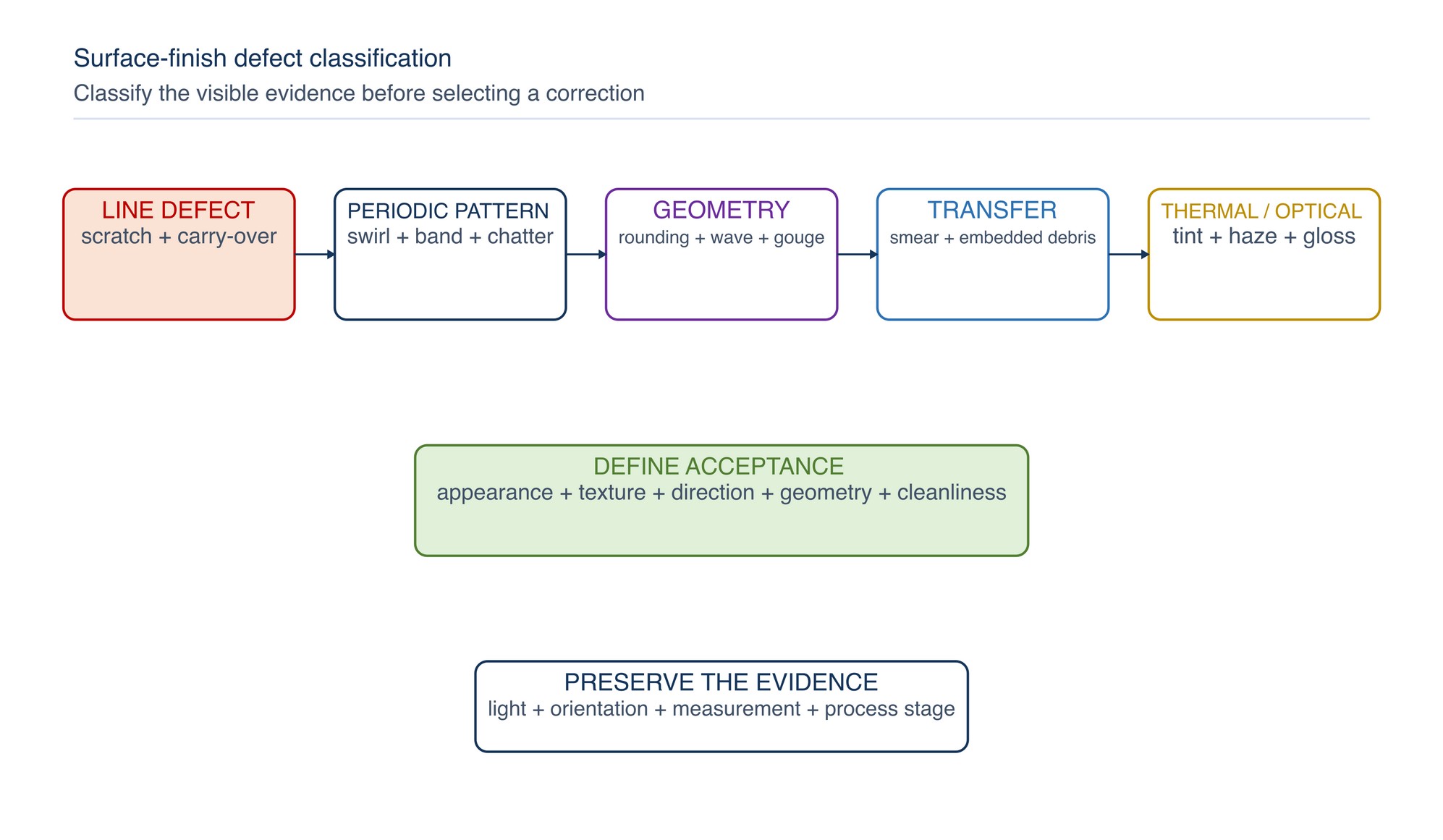
Use the visible pattern to choose the first investigation path:
| Defect family | Typical observation | First checks |
|---|---|---|
| Line or scratch | isolated deep line, old scratch remains, cross-scratch | prior-stage removal, contamination, damaged abrasive |
| Periodic pattern | swirl, banding, chatter, repeated spacing | motion, runout, support, overlap, machine condition |
| Geometry change | rounded edge, hollow, wave, low spot, gouge | backing stiffness, dwell, access angle, work support |
| Material transfer | smearing, loading marks, embedded particles | heat, product loading, cleaning, material compatibility |
| Thermal or optical | tint, burn, haze, patchy gloss or colour | heat input, sequence consistency, cleanliness, over-finishing |
Do not judge a crack, lap, seam, corrosion pit or thermal defect as a cosmetic finishing issue. Stop and refer it for the required engineering or quality assessment.
Check the complete finishing system
Abrasive grade alone does not control the result. Review:
- incoming surface condition and previous operation;
- abrasive family, grade designation, condition and sequence;
- machine type, stability, runout and power delivery;
- contact wheel, pad or backing hardness and condition;
- workholding, support and component vibration;
- contact angle, pressure, traverse, overlap and dwell consistency;
- access restrictions and operator posture;
- lubricant, coolant or extraction where applicable;
- cleaning between stages; and
- inspection timing, lighting and measurement method.
Grade designations are system-specific, and an apparent grit number does not guarantee equivalence between coated, bonded or superabrasive products. [S346–S349]
Deep scratches and scratch carry-over
Deep isolated scratches usually arise from coarse particles, damaged abrasive, trapped swarf, contaminated work support or a previous stage that was not fully removed. A random deep line appearing late in the sequence often indicates contamination rather than a need for a finer product.
Check whether the scratch:
- follows the current abrasive direction;
- crosses the current pattern and therefore predates it;
- starts at an entry point or raised feature;
- repeats with wheel or belt rotation;
- occurs where debris collects; or
- corresponds with a damaged joint, edge or backing feature.
Clean the work, tool, support and surrounding area. Replace damaged or contaminated consumables. Return to the earliest stage capable of removing the scratch without excessive stock loss, then rebuild the sequence completely.
Use a stage gate for scratch removal
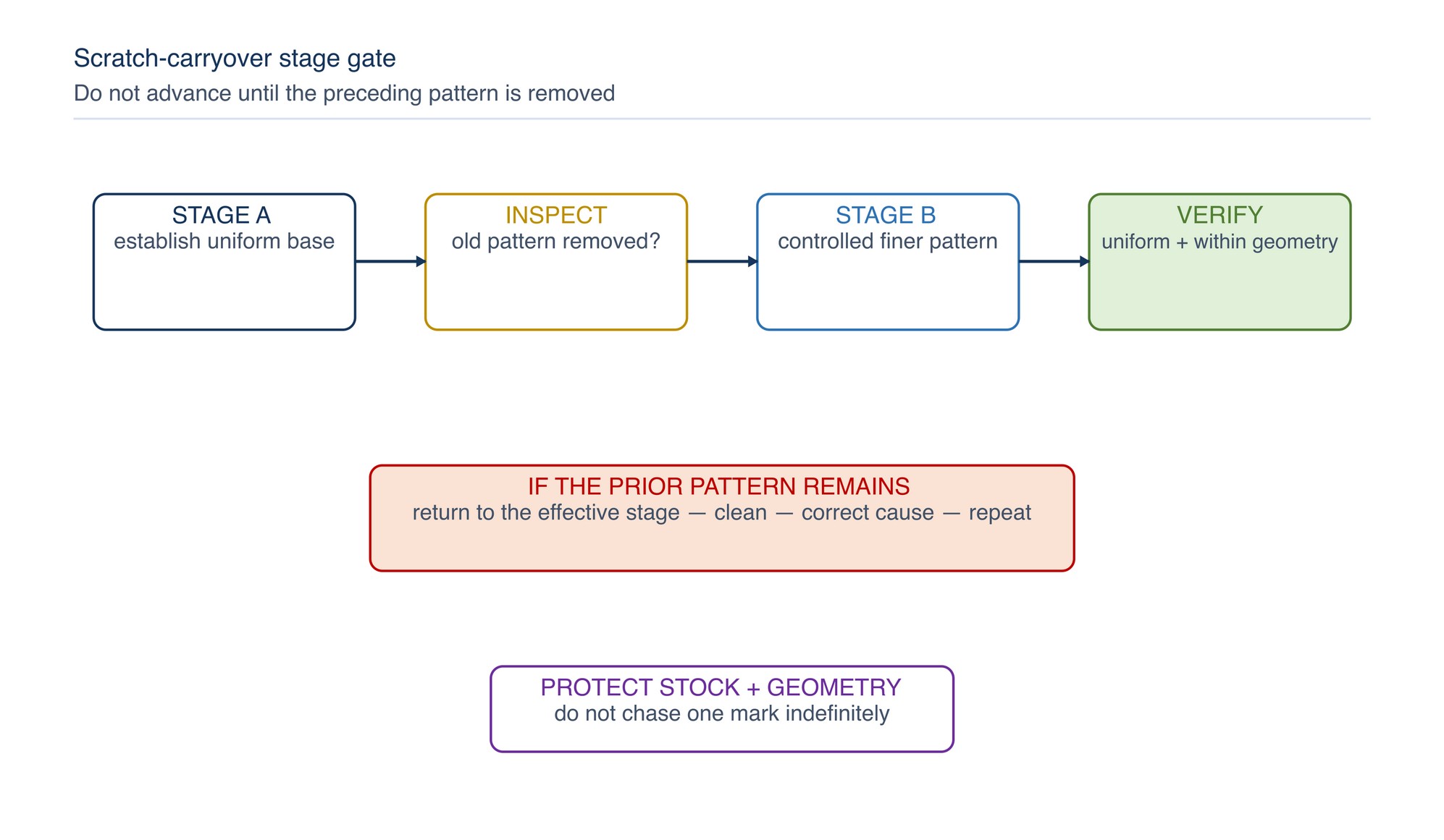
Change the working direction between stages where the component and specification permit. A changed direction makes residual scratches easier to see. Do not advance until the previous pattern has been removed throughout the controlled area. Materialographic guidance likewise emphasises complete prior-damage removal and cleaning between stages. [S123; S148–S149]
On shaped or directional finishes, a direction change may be unsuitable. Use another controlled indicator such as lighting, contrast inspection or an approved reference surface.
Swirl marks, cross-scratches and inconsistent direction
Common causes include:
- uncontrolled tool movement or changing attack angle;
- random-orbit or rotary action used where a directional finish is required;
- insufficient final passes in the specified direction;
- contact area wider than the controlled stroke;
- abrasive edge contact at starts, stops or transitions;
- local hand blending across the established grain; and
- rework that does not extend to a natural boundary.
Restore a repeatable motion and finish toward a defined boundary. Decorative stainless finishes often depend on controlled direction and uniformity, not merely abrasive grade. [S128–S131; S151]
Bands, streaks and lap lines
Bands or streaks may follow inconsistent overlap, variable pressure, product loading, uneven contact, belt tracking, coolant distribution or interruption during a pass. Determine whether the spacing matches operator strokes, wheel width, belt oscillation or a machine cycle.
Correct the mechanical or motion cause first. Use steady traverses and controlled overlap under the approved process. Avoid dwelling on a visible band: local correction can create a low spot or glossy patch that is harder to remove.
Waviness, ripple and chatter
Waviness is a longer-spacing shape variation than local roughness. Chatter often forms a repeating pattern associated with vibration or periodic motion.
Inspect:
- component clamping and unsupported span;
- machine bearings, spindle, contact wheel and drive condition;
- abrasive joint, tracking, balance and runout;
- backing compliance and contact width;
- resonance associated with a particular position;
- feed or traverse regularity; and
- interrupted contact at slots, holes or edges.
Grinding references connect chatter and poor finish to machine truth, support, dressing, vibration and thermal control. [S389; S391] Do not attempt to hide a geometric wave with finer polishing.
Edge rounding and loss of geometry
Flexible products conform readily and can remove more material at edges, corners and raised features. Edge rounding may also result from excessive dwell, steep approach, unsupported sheet or repeatedly blending the same boundary.
Before correction, confirm the permitted edge form and remaining stock. Improve support and use the least compliant contact arrangement compatible with the task. Control entry and exit so the abrasive does not roll over the edge.
Materialographic studies identify relief and edge rounding as consequences of preparation mechanics. [S148–S149]
If geometry is already below tolerance, stop further finishing and follow the applicable disposition process.
Gouges, low spots and local over-cutting
Gouges commonly begin with hard abrasive edge contact, a sudden angle change, trapped debris, excessive local force or an unstable tool. Low spots can develop when an operator chases a visual mark within a small area.
To prevent recurrence:
- approach the surface smoothly;
- maintain full intended contact support;
- keep cables and hoses from pulling the tool;
- avoid starting or stopping while an edge is digging into the work;
- blend over a sufficiently broad controlled area; and
- check thickness or contour before further removal.
Never cosmetically blend a defect if doing so could conceal unacceptable loss of section.
Smearing, loading and embedded debris
Soft, ductile or heat-sensitive materials can smear instead of cutting cleanly. Loaded abrasive can then rub, heat and redeposit material. Embedded foreign particles may originate from the abrasive, previous work, dirty handling or a shared tool.
Check product suitability, abrasive condition, contact heat, chip clearance and cleaning practice. Use material-dedicated tools where contamination control requires them. Replace a loaded or contaminated product rather than pressing harder.
Cleaning and control of preparation debris are essential between stages. [S123; S148]
Cross-contamination and rust staining
Stainless steel and other contamination-sensitive surfaces can acquire ferrous particles from shared tools, carbon-steel dust, benches, clamps or handling equipment. The stain may appear later, after moisture exposure.
Maintain segregation appropriate to the job:
- dedicated and clearly identified abrasives and brushes;
- clean work supports and handling aids;
- controlled storage away from ferrous grinding dust;
- suitable extraction and housekeeping;
- clean gloves and approved wiping materials; and
- the specified post-finish cleaning or passivation process.
Do not treat staining as proof that the base material itself is defective without investigation.
Haze, cloudiness and patchy gloss
Haze or patchiness can arise from incomplete removal of the prior pattern, uneven pressure, inconsistent dwell, contaminated media, residue, mixed abrasive condition or differences in local surface geometry. Highly reflective finishes reveal small variations strongly.
First determine whether the variation is surface texture, residue or lighting reflection. Clean by the approved method and inspect again under controlled conditions. If the texture varies, return to a stage that can establish a uniform base over the full affected zone. Tool-steel finishing guidance identifies haze and orange-peel-type effects as distinct problems with different mechanisms. [S167]
Heat tint, burn and thermal change
Unexpected colour, burn marking, local softening, distortion or heat checking requires immediate process review. Possible causes include excessive contact pressure, prolonged dwell, a loaded or dull abrasive, inadequate heat removal, unsuitable sequence or poor coolant delivery in an approved wet process.
Stop and allow safe cooling. Determine whether the component’s material, hardness, coating, corrosion performance or geometry could have been affected. Visual removal of colour does not prove removal of thermal damage. Research on grinding shows that heat, deformation and surface integrity can change together. [S084; S087]
Over-finishing and orange-peel effects
More polishing is not always better. Excessive repeated work can round geometry, create relief between microstructural constituents, reveal waviness, produce an orange-peel appearance or reduce consistency across the part. [S167]
Stop when the controlled acceptance criteria are met. Do not continue merely to increase gloss. If an orange-peel or relief pattern develops, reassess the earlier preparation and material-removal method instead of adding more final-stage dwell.
Trace causes across the process
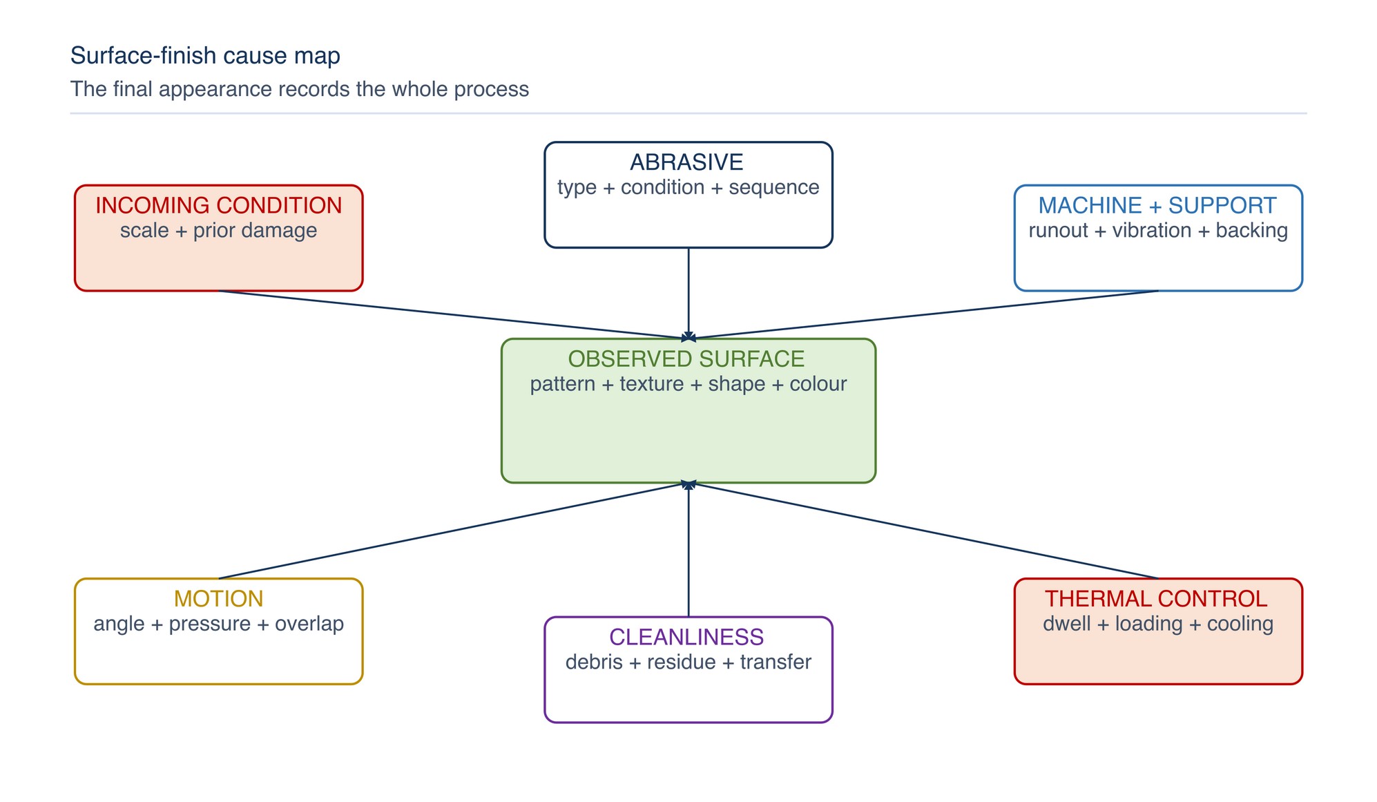
Use pattern evidence to test one cause family at a time. A repeating mark suggests a rotating or cyclic source; a boundary-aligned patch suggests local rework; a defect appearing after cleaning may be residue or contamination; a defect unchanged through several fine stages probably originated earlier or is geometric.
Apply the smallest effective correction
Use this correction sequence:
- protect people, isolate unsafe equipment and preserve evidence;
- confirm the requirement and the defect family;
- correct contamination, machine, support or motion causes;
- determine the earliest stage needed to remove the defect;
- confirm material-removal and geometry limits;
- process a controlled area with one documented change;
- rebuild the remaining sequence without skipping stage gates; and
- verify the full requirement under consistent conditions.
Changing several variables together obscures the cause. A finer product will not reliably correct waviness, contamination, a deep retained scratch or thermal damage.
Verify before release
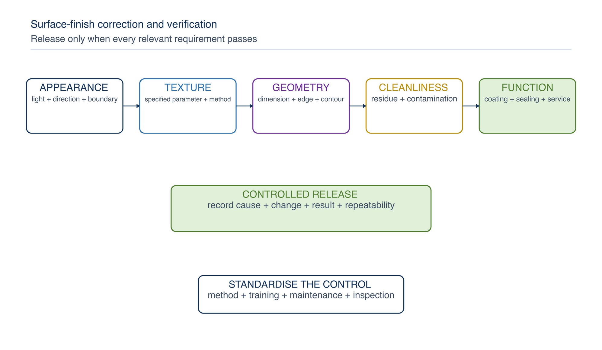
Verification may include:
- visual comparison under agreed light, distance and orientation;
- profile measurement using the specified parameter and direction;
- dimensional, flatness, contour or edge inspection;
- cleanliness and contamination checks;
- coating, bonding, sealing or hygiene readiness; and
- repeatability across more than one component or process cycle.
Record the defect, cause, controlled change and result. Update the work method, training, maintenance or consumable control when the cause is systemic.
Rapid troubleshooting table
| Symptom | Likely cause families | Controlled response |
|---|---|---|
| One deep random scratch | debris, damaged abrasive, dirty support | preserve pattern, clean system, replace affected product, return to required stage |
| Old scratches remain | stage advanced too early, inadequate coverage | restore previous effective stage and prove full pattern removal |
| Swirl or crossed direction | motion or final-pass inconsistency | restore controlled direction and boundary |
| Bands or streaks | overlap, pressure, loading, tracking or coolant variation | correct source, then refinish the complete affected zone |
| Ripple or chatter | vibration, runout, weak support, periodic motion | isolate mechanical cause before cosmetic work |
| Rounded edge | excessive compliance, dwell or rollover | confirm remaining geometry; improve support and contact control |
| Smear or embedded debris | loading, heat, contamination, unsuitable product | stop rubbing, clean and restore compatible cutting action |
| Rust stain on stainless | ferrous transfer or shared tooling | segregate tools, clean by approved process, assess contamination |
| Haze or patchy gloss | incomplete base, residue, variable pressure or dwell | standardise inspection; rebuild uniform base if required |
| Heat tint or burn | excessive heat input or inadequate cooling | stop, assess surface integrity, correct thermal cause |
| Orange peel or excessive relief | over-finishing or inadequate earlier preparation | stop final dwell and reassess preparation sequence |
Concise safety reminders
- Inspect the machine, guard, abrasive and mounting before use.
- Confirm product and machine compatibility, including marked speed limits.
- Secure the work and maintain a stable body and tool position.
- Use extraction, ventilation and respiratory protection appropriate to the dust and material.
- Control sparks, hot particles, combustible dust and nearby flammables.
- Isolate equipment before inspection, cleaning, adjustment or product change.
- Treat cracks, severe heat effects and loss of section as technical defects, not cosmetic marks.
- Follow workplace controls for hazardous coatings, stainless steel, aluminium, composites and other material-specific dusts.
Key takeaways
- Define appearance, texture, direction, geometry and cleanliness separately.
- Preserve the defect pattern before rework.
- Trace scratches and periodic marks to the earliest responsible stage.
- Correct support, motion, contamination and heat causes before changing grade.
- Do not use a finer finish to conceal waviness, thermal damage or geometry loss.
- Remove only the material necessary and verify downstream function.
- Standardise the proven correction so the defect does not return.
Polishing Problems
The Polishing Problems chapter begins on the following page of the printed handbook (page 641), outside this chapter extract.