
Paint-shop operators, finish inspectors, maintenance personnel, production engineers, EHS teams, supervisors and technical buyers
Intake and ceiling filters; exhaust and overspray arrestors; loading; pressure indication; airflow balance; bypass; collapse; contamination; overspray escape; finish defects; clearance; change-out and verification.
A booth filter is part of an engineered air-handling and fire-safety system. Diagnose the filter, its installation and the complete airflow path before changing the product or operating the booth.
Filter loading is normal, but uncontrolled loading, bypass, wrong orientation, poor support or unsuitable selection can affect coating quality, exposure control, fire risk, fan performance and emissions. A new filter does not correct a blocked intake, slipping drive, incorrect damper, dirty duct or unbalanced make-up air.
When an exact product value is required, Refer to the product label, Technical Data Sheet, or MKTECH representative.
Chapter objectives
After this chapter, the reader should be able to:
- identify booth conditions requiring immediate stop;
- distinguish supply-side, exhaust-side and installation problems;
- diagnose loading, bypass, collapse and uneven airflow;
- connect filter condition with dirt, overspray, finish and clearance symptoms;
- inspect pressure indication and the complete airflow path;
- replace filters without releasing captured residue; and
- verify airflow, capture, cleanliness and booth readiness after correction.
Immediate stop conditions
Stop spraying and follow the booth shutdown procedure when there is:
- loss of required ventilation or airflow indication;
- failed fan, drive, interlock, alarm or pressure indicator;
- visible overspray escape or vapour accumulation;
- collapsed, displaced, torn, burning or smoking filter media;
- heavy residue threatening ignition, detachment or obstruction;
- damaged filter frame, support or sealing system;
- solvent, paint or water release into electrical or unsafe areas;
- unexpected odour or exposure outside the controlled zone; or
- doubt about the booth’s safe operating condition.
Do not bypass an interlock or operate beyond the booth manufacturer’s filter or pressure condition.
Map the complete air path
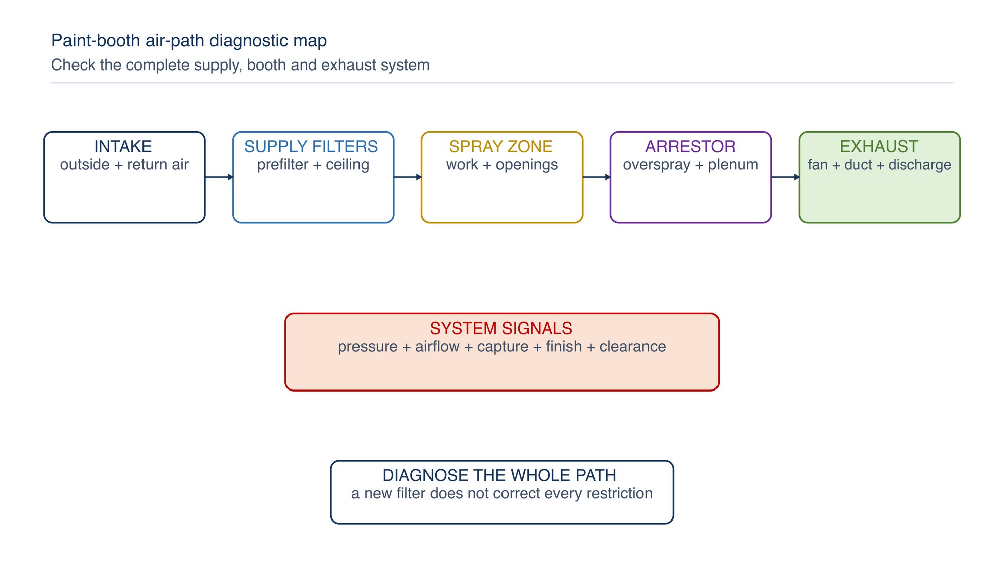
Trace air through:
- outdoor or return-air intake where designed;
- prefilter and supply filtration;
- fan, heating or conditioning section;
- ceiling, wall or final supply filter;
- occupied spray zone and workpiece;
- floor, wall or plenum overspray arrestor;
- exhaust fan, duct and discharge; and
- make-up-air and building-pressure relationship.
A restriction or leak at any point can alter the booth pattern.
Confirm filter identity and intended position
Check:
- exact filter family and dimensions;
- intake, ceiling, exhaust or overspray duty;
- airflow-direction marking;
- frame, pocket, pad, roll or panel format;
- support grid, retaining hardware and gasket arrangement;
- media condition, storage and contamination;
- compatibility with coating, booth and fire controls; and
- replacement instructions for the installed booth.
General-ventilation filter classifications do not automatically describe paint-arrestor capture, holding or fire behaviour. [S181–S183]
Use a symptom-led sequence
Start with the observed problem, then check:
- pressure indication and recent trend;
- visual filter condition and installation;
- intake and make-up-air availability;
- fan, drive, damper and duct condition;
- booth residue and obstruction;
- coating or production change; and
- verified airflow pattern and clearance.
Record the filter position, date, production condition and symptom before change-out. Do not diagnose from filter colour alone.
Rapid or unexpected pressure rise
Possible causes include:
- high overspray or dust loading;
- coating, gun, transfer-efficiency or production change;
- filter installed in the wrong direction;
- media compressed, folded or insufficiently expanded;
- wet, sticky or prematurely blinded media;
- blocked downstream layer or plenum;
- damper or duct restriction; and
- pressure tubing or instrument fault.
Pressure is a system signal, not an isolated filter verdict. EPA and fan-system guidance connect filter loading with increasing resistance and changing airflow. [S178–S179]
Low or falling pressure indication
An unexpectedly low reading can indicate:
- torn or missing media;
- filter bypass around a frame;
- collapsed or displaced filter;
- fan, belt, motor or drive loss;
- blocked pressure tube or wrong tapping condition;
- open access panel or duct leak; or
- changed damper or make-up-air condition.
Low resistance is not automatically good performance. Inspect for loss of capture and system integrity before spraying resumes.
Uneven airflow across the booth
Common causes include uneven filter loading, mixed filter condition, gaps, incorrect orientation, blocked ceiling sections, poor plenum distribution, fan or damper condition, open doors, building drafts and obstructed exhaust zones.
Look for coating drift, moving masking paper, uneven overspray deposits or local dead zones. Use the booth’s approved airflow verification method; do not rely on hand sensation alone.
Dirt, fibres or particles in the finish
Investigate:
- damaged or unsuitable supply filters;
- bypass at frames, seams, doors or access panels;
- dirty plenum, duct, booth or compressed-air source;
- shedding media or disturbed accumulated dust;
- contaminated clothing, masking, workpiece or handling;
- filter change performed without controlled cleaning; and
- excessive booth pressure drawing contamination from adjacent areas.
Changing the exhaust filter alone will not correct supply-side dirt. Preserve defect samples and trace particle type and location.
Overspray escape or poor capture
Possible causes include loaded exhaust filters, bypass, missing media, inadequate fan output, slipping drive, obstructed duct, incorrect damper, blocked discharge, excessive spray generation or a disturbed booth opening.
Dry-filter and water-wash booths require different checks. OSHA spray-finishing guidance recognises continuing mechanical ventilation and controlled overspray-residue removal as core system functions. [S175]
Stop if visible material escapes the intended capture zone.
Filter bypass and poor sealing
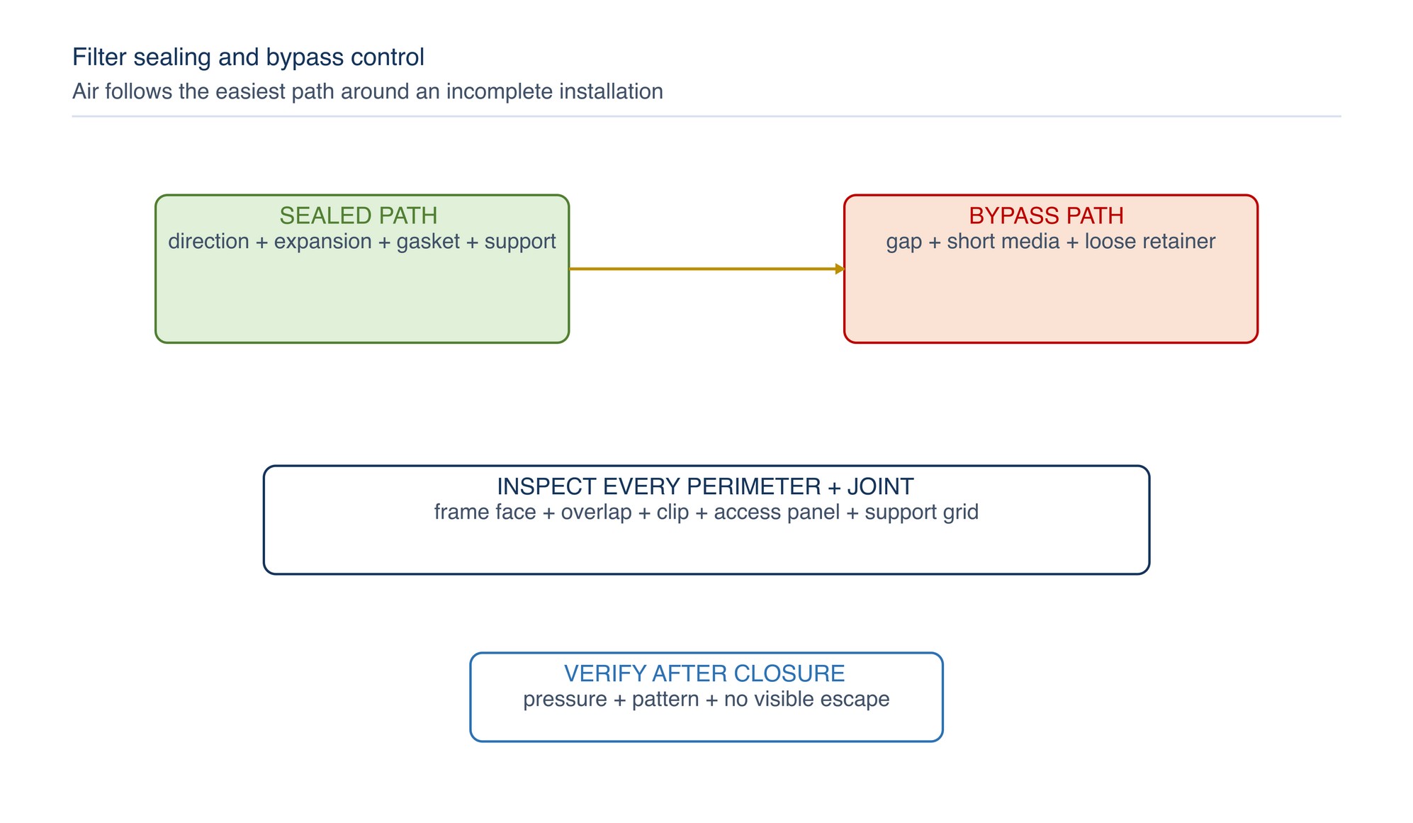
Inspect the full perimeter and all joints for:
- missing, damaged or compressed gasket;
- warped frame or dirty sealing face;
- short-cut media or inadequate overlap;
- open seams between pads or panels;
- loose clips, retainers or support;
- incorrect pocket or pad seating; and
- access panel or service-door leakage.
Manufacturer installation guidance consistently emphasises direction, gasket compression, frame fit and joint sealing. [S187; S195–S196]
Reversed, compressed or poorly expanded media
Some paint-arrestor media depend on staged density, open structure, pocket form or labyrinth geometry. Reversal or compression can change capture and resistance. Roll media may require full designed expansion and secure support.
Follow the filter marking and installation instructions. Do not infer orientation from colour alone. Paper-labyrinth products require the intended expansion and orientation to form their separation path. [S187]
Collapse, sagging and media movement
Collapse may follow missing support, incorrect retaining method, wet loading, excessive system condition, damaged media or poor fit. Movement can open bypass paths and release captured residue.
Stop the system before safe inspection. Correct the support or frame cause, clean escaped residue under the approved method and replace affected media. Do not add improvised wire, combustible material or unapproved fasteners inside the booth.
Short filter life
Review the whole process:
- coating and solids content;
- spray equipment condition and transfer practice;
- production volume and part geometry;
- booth cleaning and residue control;
- filter area and installation;
- upstream dust or moisture;
- fan and airflow balance; and
- whether the filter is being changed by condition or by appearance alone.
Do not claim a universal service interval. Compare like-for-like production and controlled pressure or airflow trends.
Fan strain, noise or energy increase
Loaded filters increase system resistance and can move the fan away from its intended operating condition. Abnormal noise, vibration, motor load, belt condition or reduced flow also can arise from mechanical defects or duct restriction. [S179]
Stop and involve competent maintenance when fan or drive condition is abnormal. A higher-capacity fan is not a routine remedy for an unsuitable or obstructed system.
Extended or uncertain clearance time
Clearance time is the period required after spraying stops for airborne mist or vapour to be removed to the controlled criterion. Filter loading, airflow imbalance, leakage and process change can affect it.
HSE guidance recommends clearance verification under representative adverse conditions, including filter loading, and checking for leakage. [S176] Use the booth’s posted and validated clearance control. Do not enter early because the booth looks clear.
Change filters as a controlled task
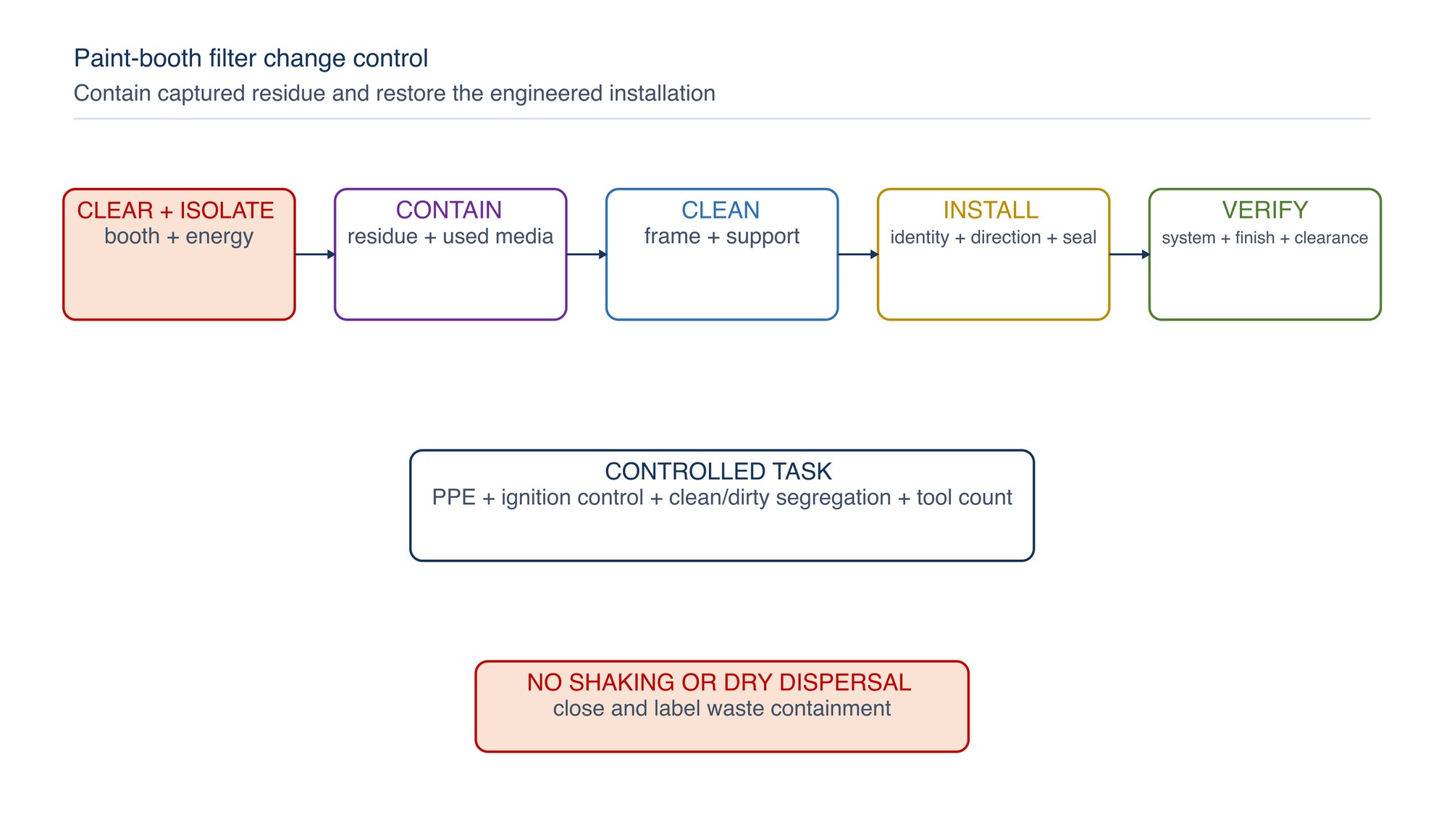
Before change-out:
- stop spraying and complete the required clearance;
- isolate relevant energy under the work method;
- prepare compatible replacement media and tools;
- control ignition sources and static risks;
- wear PPE for the coating and residue hazards;
- protect clean supply areas from dirty exhaust media; and
- prepare labelled containment for used filters.
Remove media without shaking captured residue. Clean sealing faces and supports without dispersing dust. Install in the marked direction, secure all joints and account for tools and loose material before closure.
Avoid mixed-condition filter banks
Replacing isolated panels in a bank can create uneven resistance if the booth design expects a matched set. Local new-versus-loaded sections may distort airflow.
Follow the booth and filter instructions for bank replacement. If partial replacement is permitted, record locations and verify the full pattern. Never mix unconfirmed filter families merely because dimensions appear similar.
Handle used filters and residue correctly
Used filters can contain paint solids, solvent, metal pigment, isocyanate-related residue or other hazardous material. Prevent ignition, incompatible mixing, leakage and unauthorised reuse.
Waste classification follows the actual coating and process. Refer to current Department of Environment Malaysia scheduled-waste requirements and competent site procedures. [S189] Do not label all used filters identically without checking the residue source.
Verify after correction
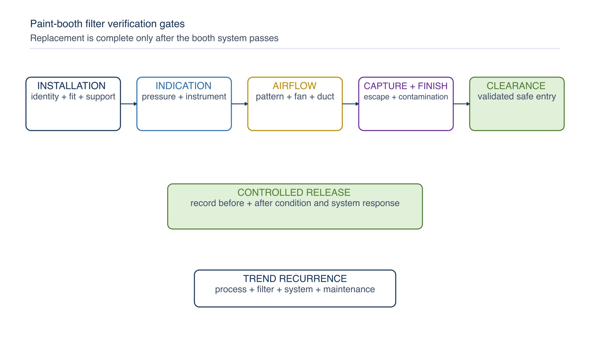
Verify as applicable:
- correct filter identity, direction, fit, support and sealing;
- clean plenum, frame and booth condition;
- pressure indication and tubing condition;
- fan, drive, damper, duct and discharge condition;
- approved airflow pattern or capture test;
- no visible bypass, collapse or overspray escape;
- coating finish under a controlled check; and
- validated clearance and safety-system function.
Record the condition before and after change. A new filter is not proof that the booth is ready.
Rapid troubleshooting table
| Symptom | Likely cause families | Controlled response |
|---|---|---|
| Pressure rises rapidly | loading, reversal, compression, wet media, obstruction | inspect complete path and recent process change |
| Pressure unexpectedly low | bypass, tear, fan loss, instrument fault | stop, verify integrity and airflow before use |
| Uneven airflow | mixed loading, gaps, plenum, damper, drafts | restore installation and system balance |
| Dirt in finish | supply filter, bypass, plenum, clothing, handling | identify particle source; clean and seal controlled areas |
| Overspray escapes | exhaust loading, bypass, fan or duct problem | stop spraying and restore capture system |
| Media collapses | support, fit, wet loading or excessive condition | isolate, contain residue, correct support and replace |
| Filters load too quickly | spray process, production, area, moisture or wrong selection | compare controlled production and system trend |
| Clearance takes longer | loading, imbalance, leakage or process change | revalidate under approved method before entry |
Concise safety reminders
- Never spray without the required mechanical ventilation and safety controls.
- Do not bypass pressure indication, alarms, interlocks or fire-protection systems.
- Complete booth clearance before entry or filter work.
- Control ignition, static, solvent vapour, isocyanate and combustible-residue hazards.
- Isolate fans and moving equipment before access.
- Use PPE and respiratory controls for the actual coating and cleaning materials.
- Keep clean supply filters separated from contaminated exhaust media.
- Contain and classify used filters according to the actual residue and current requirements.
Key takeaways
- Treat the filter as part of the complete booth airflow system.
- High and low pressure signals can both indicate unsafe or poor-control conditions.
- Check orientation, expansion, support and sealing at every change.
- Diagnose supply-side dirt separately from exhaust-side capture.
- Never use appearance alone to set filter change timing.
- Verify airflow, capture, finish and clearance after correction.
- Classify used filters from the actual coating residue.
Chemical Problems
Chapter 072 begins on the following page of the printed handbook (page 659), outside this chapter extract.