
Production engineers, supervisors, operators, QA/QC personnel, maintenance teams, safety personnel, procurement staff and technical sales personnel
Coarse, medium, fine and micro-finishing abrasive stages; FEPA P-grades; grit progression; scratch formation, removal and inspection. This chapter does not approve an MKTECH SKU, universal grit sequence, scratch depth, removal allowance, speed, pressure, dwell time or acceptance limit.
Verify the complete abrasive product, work material, machine, mounting, guard, dimensions, maximum operating speed and current manufacturer instructions before use. Stop for an unknown product, damaged abrasive, missing marking, incompatible machine, unverified coating or unapproved dust control. Grit number alone never authorises an application. [S032]
Chapter objectives
After this chapter, the reader should be able to:
- distinguish functional coarse, medium, fine and micro-finishing stages without treating them as universal numeric bands;
- explain what a FEPA P-grade does and does not specify;
- recognise why equal-looking numbers from different grit systems may not be equivalent;
- describe how grain size, shape, distribution, support and contact affect scratch topography;
- plan a progression in which each stage removes the previous stage's unwanted scratches;
- identify the risks of an excessive grit jump;
- inspect a directional surface using controlled cleaning and changing light direction; and
- release a sequence only after representative trials and defined acceptance checks.
A grit number describes a grading system, not the finished surface
Grit designations classify abrasive grain size within a defined standard or manufacturer system. They do not directly state the depth of every scratch, the roughness value of the finished surface or the amount of material that one pass will remove.
A real scratch is created by the grains that actually protrude and engage the workpiece. Grain shape, size distribution, orientation, bond or adhesive, backing compliance, product wear, loading, contact pressure, speed, contact area, motion, lubricant, work-material hardness and pre-existing damage all change the result. A nominally finer product can still leave an isolated deep line if a coarse particle, detached chip or contamination becomes trapped at the interface. [S025; S029]
Therefore, use the complete product identity and its declared grading system. Never compare two labels by number alone.
Functional grit stages
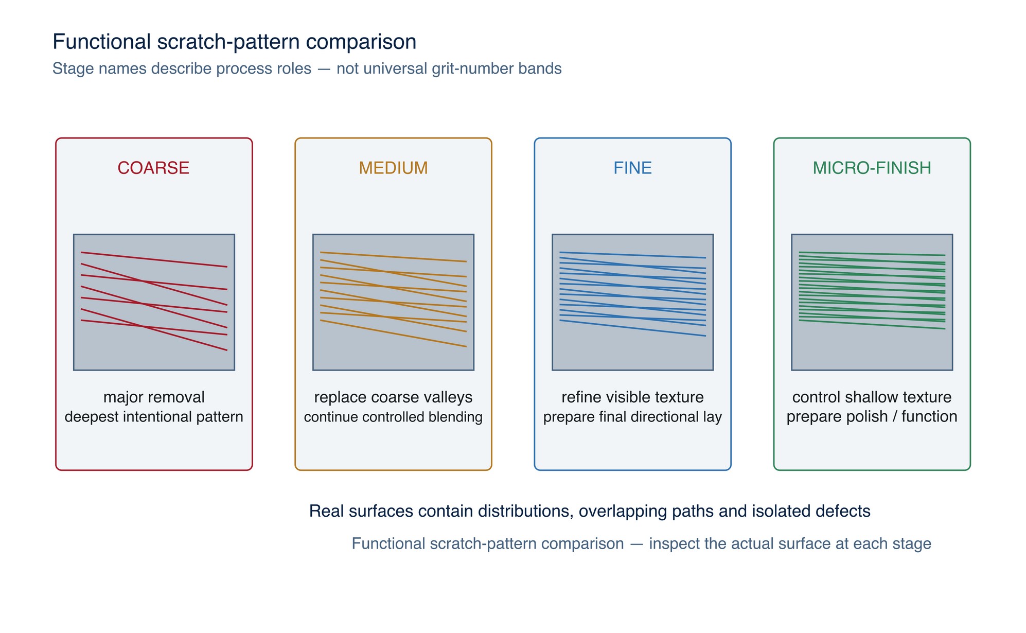
The words coarse, medium, fine and micro-finishing are useful process roles, not fixed international bands.
Coarse stage
The coarse stage removes scale, weld excess, coating, damage or unwanted geometry. It normally establishes the deepest intentional scratch pattern in the sequence and consumes the greatest material allowance. Starting coarser may shorten initial removal time but increases the work required later to remove the deepest valleys.
Medium stage
The medium stage converts the coarse pattern into a more uniform and shallower texture while continuing limited blending or shaping. It should not be expected to correct large geometric errors economically if the coarse stage was stopped too early.
Fine stage
The fine stage refines visible scratches, reduces texture contrast and prepares the surface for the specified directional, coating, polishing or functional finish. At this point contamination, inconsistent contact and local dwell become increasingly visible.
Micro-finishing stage
Micro-finishing uses very fine graded abrasives or engineered finishing products to control a shallow texture, prepare for polishing or meet a defined surface-function requirement. “Micro-finish” is not proof of mirror appearance or a roughness value. The product system, process and measurement method still control.
FEPA P-grades
FEPA distinguishes abrasive-product families by designation: F-grit sizes for bonded abrasives, P-grit sizes for coated abrasives, and D or B prefixes for diamond or cBN superabrasives. FEPA also explains that a macrogrit diameter is controlled as a distribution rather than one single particle diameter. [S039]
The current ISO coated-abrasive standards divide P-grades into macrogrits P12 to P220 and microgrits P240 to P5000 for electro-fused aluminium oxide and silicon carbide. ISO 6344-2:2021 covers macrogrit distribution and designation; ISO 6344-3:2021 covers microgrits. [S040; S041]
Read a P-grade correctly:
- the P prefix identifies the coated-abrasive grading family;
- the number is a designation within that family, not a measured scratch depth;
- a higher P number generally represents a finer nominal grade within the P system;
- the grade controls a particle-size distribution, not identical grains; and
- the complete coated product still includes grain type, coating density, backing, adhesive, treatment and geometry.
Do not use an F-grade table, a bare mesh number or a supplier's informal “grit” label as if it were automatically a P-grade equivalent.
P-grade and other grit systems
ANSI/CAMI, JIS, FEPA F, FEPA P, micron-labelled films and proprietary finishing scales can use similar numbers for different particle distributions. Conversion charts are approximations for shortlisting, not proof that two products will cut or finish identically. The differences can become more important at fine and microgrit sizes. [S039; S043]
For a substitution or cross-supplier comparison, record:
- the full standard or grading system;
- the exact grade and product code;
- abrasive mineral and construction;
- backing, bond or film type;
- open/closed coating or other distribution feature;
- intended material and application; and
- the representative trial result.
If the grading system is missing, treat the product as unidentified for sequence design.
How scratch depth is created
Abrasive grains create many overlapping grooves. Each active grain can cut, plough or rub. The resulting surface contains peaks, valleys, displaced material, torn material and occasional isolated defects. The deepest observed line may come from the largest effective protrusion or contamination rather than the nominal average grain.
Scratch depth tends to increase with larger effective cutting points and deeper engagement, but it is not a fixed fraction of particle size. A compliant backing can follow surface geometry while also changing local contact. A worn or loaded product can rub, smear or trap debris. A rigid, sharp product can cut a more defined pattern. Work-material hardness and ductility affect whether material is separated, displaced sideways or smeared.
This is why a visual “looks fine” check is insufficient for a controlled specification. When surface function matters, define an appropriate measurement such as comparator assessment, surface roughness, profile, microscopy, coating adhesion or customer-approved reference panels.
The purpose of grit progression
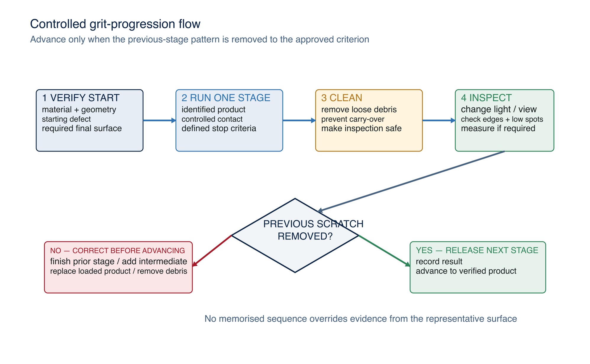
A progression is a sequence of controlled surface-generation stages. Each finer stage must remove the unwanted valleys and damaged layer left by the previous stage while preserving required geometry.
The governing question is not “What number comes next?” It is “Can this complete next-stage product remove the remaining deepest defects within the permitted time, heat, edge change and material allowance?”
A robust sequence has four controls:
- entry condition: the starting defect and geometry are known;
- stage objective: the pattern that must be removed or created is defined;
- inspection gate: the surface is cleaned and checked before changing products; and
- exit condition: no previous-stage scratch remains above the approved acceptance threshold.
Risks of an excessive grit jump
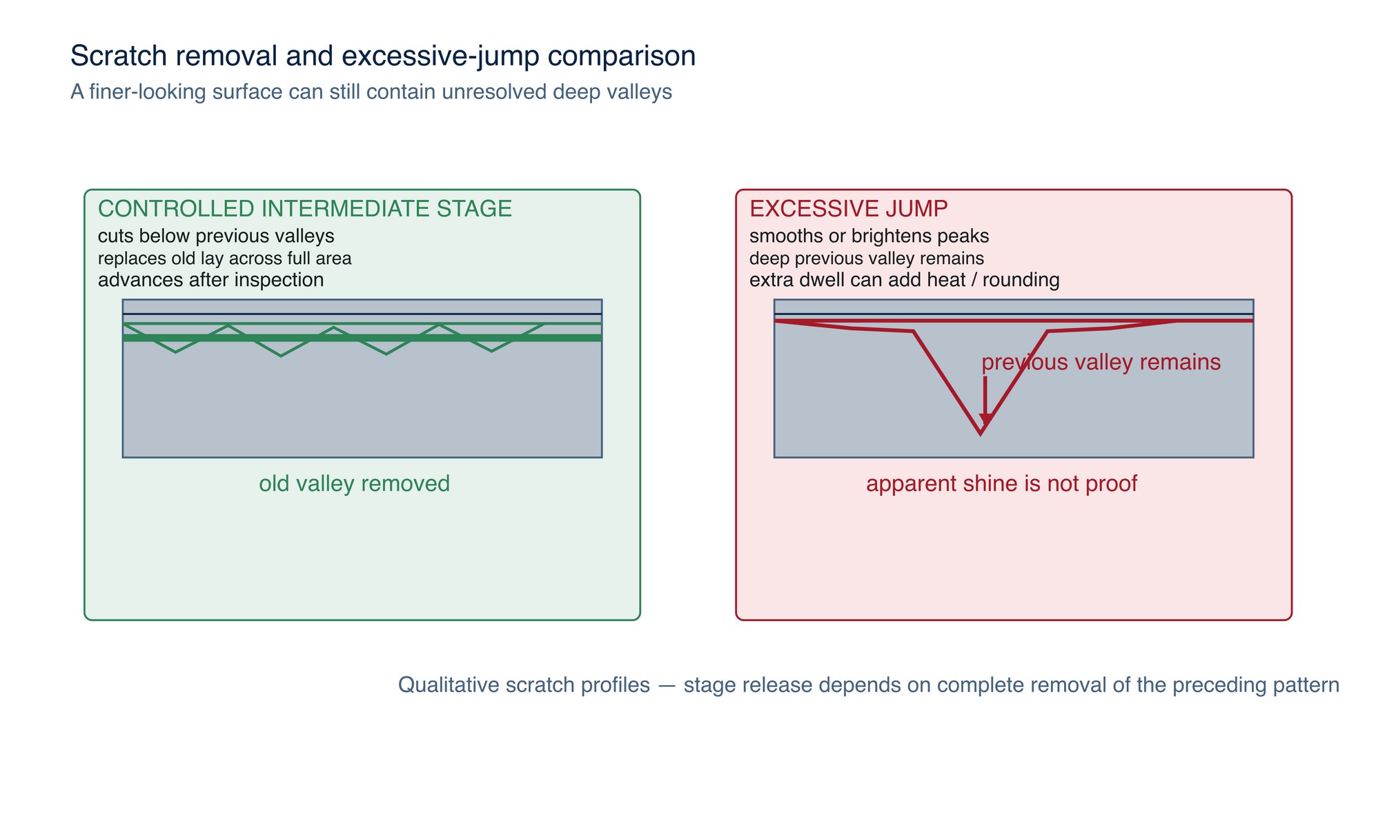
An excessive jump occurs when the next stage lacks enough cutting capacity to remove the previous stage's deepest scratches within the controlled process window. A large numerical gap is not automatically excessive, and a small gap is not automatically safe; the result depends on both products and the work.
Common failure modes include:
- polishing the peaks while deep coarse valleys remain;
- extending dwell or force until heat, distortion or edge rounding develops;
- using many fine consumables to do work that belongs to an intermediate stage;
- leaving isolated coarse scratches that appear only after coating or final lighting;
- losing the original directional pattern through random corrective motion; and
- misreading temporary shine or smear as scratch removal.
If the finer stage is slow, do not automatically increase force. Stop, clean, inspect and decide whether the previous stage was complete, an intermediate stage is needed, the abrasive is loaded or worn, contamination is present, or the product construction is unsuitable.
Alternating direction as an inspection aid
Where geometry and the required final lay permit, change the working direction between consecutive stages. A new directional pattern makes residual scratches from the previous stage easier to distinguish. Do not use this method where the product, joint, edge, machine or specified grain direction prohibits cross-working.
Direction change is an inspection aid, not a substitute for complete coverage. The stage is complete only when the old-direction lines are removed to the approved criterion across the entire controlled area, including edges, transitions and low spots.
For a final directional finish, the last approved stage must re-establish the specified lay consistently. British Stainless Steel Association guidance notes that mechanically polished stainless finishes are directional and that appearance depends on process variables; a descriptive grit label alone does not define the result. [S028]
Inspection under directional lighting
Use a repeatable inspection method:
- Stop the machine and make the area safe.
- Remove loose abrasive debris with the approved cleaning method; do not wipe contaminated particles back across the surface.
- Use a clean, controlled light source at a shallow angle to the surface.
- Inspect with the light across the scratch direction, then change the light or viewing direction.
- Mark isolated previous-stage scratches without damaging the acceptance area.
- Check edges, curves, weld transitions and shadowed zones separately.
- Compare with the approved reference panel or measurement requirement.
- Record the product, grade system, stage, surface condition and result before continuing.
Directional lighting increases visual contrast but does not measure depth. Scratch patterns can be compared visually, while objective profiling can reveal depth and consistency that a casual view cannot quantify. Use visual screening to locate defects and the specified measurement method to assess controlled surface requirements. [S042]
Controlled progression table
| Stage role | Primary purpose | Evidence before advancing | Typical failure signal |
|---|---|---|---|
| Coarse | Remove major defect or geometry | Defect removed; allowance and heat remain controlled | Deep isolated gouges, edge loss, tint or distortion |
| Medium | Replace coarse texture with uniform shallower lay | Coarse-direction scratches removed across the area | Bright peaks with persistent coarse valleys |
| Fine | Create coating-ready, directional or pre-polish surface | Uniform appearance under changed light direction; defined measurement passes | Swirls, contamination lines, patchiness or over-blending |
| Micro-finishing | Control shallow texture or prepare for polish | Approved comparator or instrumental criterion passes | Shine without uniformity; embedded debris; unresolved deeper marks |
The stage names do not prescribe grit numbers. Use the product manufacturer's sequence guidance and confirm it on representative material.
Controlled trial and release
- Verify material grade, hardness, coating, geometry, starting damage and required final surface.
- Record the complete abrasive product, grading system and grit designation for every proposed stage.
- Define speed, contact, motion, cooling, extraction and replacement criteria from current product and machine data.
- Prepare a representative trial coupon or non-critical area with the same material condition and geometry.
- Photograph and, where required, measure the starting condition.
- Run one stage at a time with controlled technique.
- Clean and inspect under at least two useful light/viewing directions.
- Record whether the previous-stage pattern has been removed, along with time, consumable use, heat, geometry and surface result.
- Add an intermediate stage or revise the product if the next stage cannot remove the deepest defects inside the allowed window.
- Release the sequence only after technical, safety, quality and MKTECH approval.
Building an application-specific grit sequence
Begin with the least aggressive grade that removes the stated defect or allowance efficiently. Add only the refinement stages needed to replace the previous scratch pattern and reach the specified visual or measured finish. Inspect under consistent lighting and change direction between stages where the geometry permits.
Do not treat FEPA P, FEPA F, ANSI/CAMI, JIS, micron and proprietary grades as directly interchangeable. Verify the grading system printed for the exact product and compare the complete process on representative material. Refer to the product label, Technical Data Sheet, or MKTECH representative.
Abrasive Product Construction
The product-construction grid appears on the following page of the printed handbook (page 58), outside this chapter extract.