
Production engineers, supervisors, operators, QA/QC personnel, maintenance teams, safety personnel, procurement staff and technical sales personnel
Bonded, coated, non-woven and structured abrasive construction; flexible grinding discs; grinding and cutting wheels; flap, fibre and sanding discs; belts, sheets, rolls, mounted points, non-woven wheels and polishing products. This chapter does not approve an MKTECH SKU, product substitution, machine, mounting system, speed, angle, pressure, duty cycle or finish result.
Product shape alone does not establish safe use. Verify the complete product identity, dimensions, mounting, wheel or disc type, guard, backing pad or flange, direction, maximum operating speed, machine compatibility and current manufacturer instructions. Do not use an unknown, damaged, expired where applicable, wet-damaged, distorted, delaminated or incorrectly mounted abrasive. [S032]
Chapter objectives
After this chapter, the reader should be able to:
- distinguish construction family from product format;
- identify the working layers in bonded, coated, non-woven and structured abrasives;
- explain the functions of backing, make or base coat, abrasive layer, size coat, bond, pores, reinforcement and optional top coatings;
- recognise how grinding wheels, cutting wheels, flexible discs, flap discs, fibre discs, sanding discs, belts, sheets, rolls, mounted points and non-woven wheels package those constructions;
- identify when an attachment, hub, backing plate, shank or reinforcement is load-bearing;
- screen products for construction damage before use; and
- select candidates for a controlled trial without inferring performance from shape, colour or product name alone.
Why construction matters
An abrasive product is a load path as well as a cutting surface. Contact force travels from the machine through a flange, pad, hub, shank, backing or wheel body to the active abrasive. Heat and debris must leave through the work contact, the product structure, coolant or the surrounding air. Wear must expose or release cutting points without uncontrolled separation.
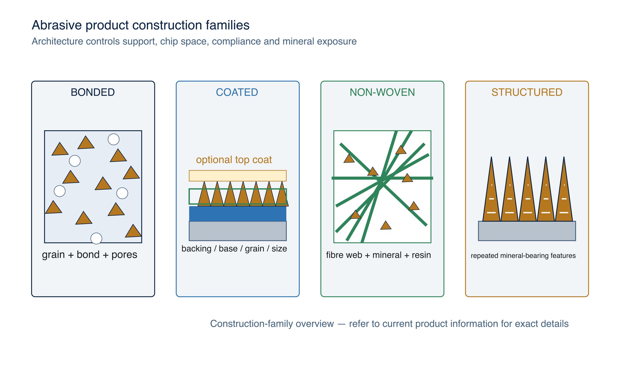
Construction determines how those functions are shared. A rigid bonded wheel carries load through a three-dimensional body of grain, bond and pores. A coated abrasive anchors grain to a flexible backing. A non-woven product distributes mineral through an open fibre network. A structured abrasive places mineral inside repeated three-dimensional features on a carrier. Products that look similar from the working face can therefore differ greatly in stiffness, grain support, debris clearance, edge behaviour, mounting and failure mode. [S029; S033; S044-S046]
The practical rule is simple: identify the architecture, the format and the attachment separately.
Four construction families
Bonded abrasives
In a bonded abrasive, abrasive grains are held throughout a shaped body by a bonding agent. Voids or deliberately controlled porosity separate parts of the grain-and-bond network. The principal wheel components are abrasive grain, bond and air space; a superabrasive layer may instead be carried on a separate hub or core. [S033]
The bond retains grains and transmits force. The pores provide chip space and paths for coolant or air, while the abrasive grains create the cutting points. Bonded does not mean one bond chemistry: vitrified, resin and other systems behave differently, and the complete manufacturer specification controls.
Coated abrasives
A coated abrasive normally has a backing, a first adhesive layer, abrasive grit, a size coat and sometimes an additional coating. The base coat positions the grain; the size coat bonds the grains to one another and to the backing. Backing options include paper, cloth, film, vulcanised fibre, foam and combinations, each contributing different flexibility, stretch, tear resistance, tensile strength and stability. [S044]
The optional top coating may alter loading, friction, cooling or grinding behaviour, but its chemistry and intended material must be verified from the product data. A visible colour is not a reliable identifier of that coating.
Non-woven abrasives
In a typical non-woven abrasive, mineral is bonded into a network of synthetic fibres rather than coated as one dense, flat grain layer. Open-web constructions combine abrasive mineral, non-woven fibres and a bonding system; spaces in the web allow swarf to escape, while progressive fibre wear can expose fresh mineral. [S045]
The open and compliant structure can follow contours and reduce the tendency to gouge, but non-woven is not automatically a light-duty product. Web density, fibre size, mineral, resin, compression and product geometry can produce hand pads, belts, discs, convolute wheels or compressed unitised wheels with very different stiffness.
Structured abrasives
Structured abrasives place graded mineral in engineered features rather than relying only on a random single-layer grain distribution. Precisely formed three-dimensional abrasive structures can be designed to expose fresh mineral progressively as they wear. The feature geometry and grading system remain product-specific. [S046]
The feature geometry, mineral distribution, carrier and grade system are product-specific. A structured product must not be assigned a FEPA P-grade or treated as equivalent to conventional coated paper unless the manufacturer declares that relationship.
Product format is not construction family
Terms such as disc, wheel, belt, sheet and roll describe geometry or delivery form. They do not by themselves identify the abrasive architecture.
| Product form | Common construction possibilities | Construction questions to verify |
|---|---|---|
| Grinding wheel | Bonded grain-bond-pore body; sometimes reinforced resin; superabrasive layer on a core | Bond system, structure, reinforcement, wheel type, dimensions and mounting |
| Cutting wheel | Thin bonded wheel, often resin-bonded and reinforced for its declared machine and cut restriction | Wheel type, reinforcement layout, side-load restriction, flanges and machine class |
| Flexible grinding disc | Resin-bonded abrasive body with engineered reinforcement and controlled flexibility | Disc type, support, permitted surface, guard and mounting |
| Flap disc | Overlapping coated-abrasive flaps fixed to a backing plate or hub | Flap material, arrangement, plate material, adhesive, shape and wear limit |
| Fibre disc | Coated abrasive on heavy vulcanised-fibre backing, used with a compatible backing pad | Disc and pad diameter, hole or attachment, backing condition and rated speed |
| Sanding disc | Paper, film, cloth, mesh or non-woven construction with PSA, hook-and-loop or mechanical attachment | Backing, coating density, hole pattern, attachment and pad interface |
| Belt, sheet or roll | Usually coated abrasive; may also be non-woven or structured | Backing, joint or edge, width, direction, waterproof status and storage condition |
| Mounted point | Small bonded abrasive body fixed to a shank or spindle | Shape, shank size, overhang, rated speed and runout |
| Non-woven wheel | Open web, convolute web or compressed/unitised layers around a centre or hub | Density, direction, bore or shank, side exposure and wear limit |
| Polishing product | May be structured abrasive, non-woven, bonded compound, loose compound plus buff, film or pad system | Carrier, compound, lubricant, contamination control and required final criterion |
Fibre, flap, hook-and-loop, pressure-sensitive adhesive and quick-change discs may share a general disc format, but their structures, support requirements and attachments differ. Fibre discs use a coated abrasive layer on a strong fibre backing, while flap discs use overlapping abrasive flaps fixed to a backing plate. [S047]
Bonded wheels, cutting wheels and flexible discs
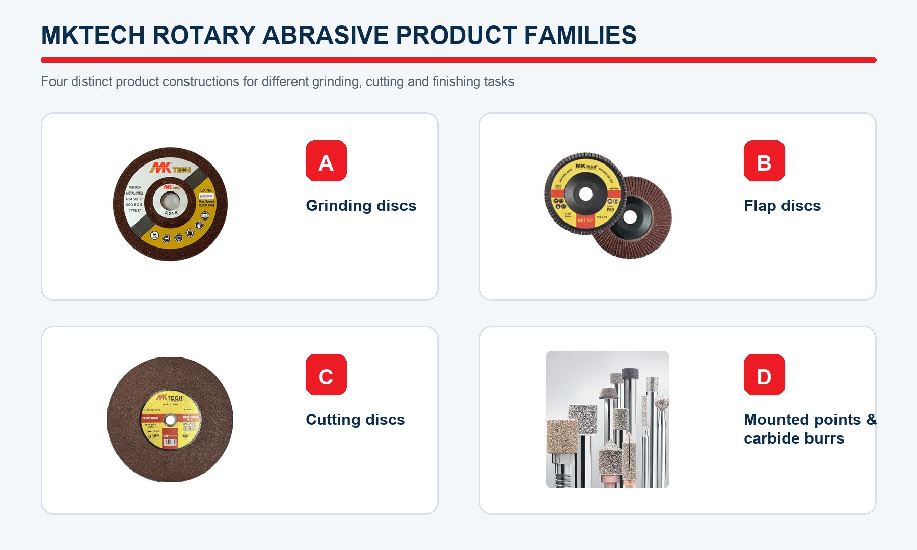
Grinding wheels
A conventional bonded grinding wheel is a three-dimensional composite. Grain type and size describe only part of it; bond type, bond strength, grade, structure or porosity, dimensions and wheel shape determine how the wheel supports grains and clears chips. [S029; S033]
Do not confuse wheel hardness with abrasive-mineral hardness. In wheel terminology, grade commonly describes the strength with which the bond holds the grain, while structure describes the spacing of grains. Exact codes vary by manufacturer and must be read from the controlled specification.
Cutting wheels
A cutting wheel is thin because it must create a narrow kerf, not because it is a general-purpose side-grinding wheel. Reinforcement is an engineered part of some products, not permission to apply side load. Wheel type, reinforcement, mounting and declared machine class must always be read together; a wheel intended for a stationary chop saw must not be transferred to a portable cut-off machine unless the product marking and manufacturer instructions expressly permit it. [S048]
Flexible grinding discs
Flexible bonded discs use a bond and reinforcement system designed to permit controlled conformance while transmitting load. Their flexibility, permitted working surface and support method are part of the specification. Never flex, trim, stack or mount a disc merely because another product of similar diameter tolerates that practice.
Mounted points
A mounted point packages a small bonded body on a shank for internal or local work. The shank, bond body and interface form one rotating system. Shank diameter, mounted overhang, point shape, machine collet and maximum operating speed must be compatible; a point must not be treated as a miniature wheel with automatically transferable wheel settings.
Coated formats
Fibre discs
The heavy vulcanised-fibre backing of a fibre disc supports an aggressive coated layer but normally depends on a compatible backing pad during use. Moisture damage, cupping, edge cracking, an incorrect pad or incomplete seating changes how load reaches the abrasive. A fibre disc is not a cutting wheel and is not self-supporting merely because it is stiff in the hand. [S047]
Sanding discs
Sanding discs may use paper, cloth, film, mesh, foam-laminated or other backings. Their attachment may be pressure-sensitive adhesive, hook-and-loop, centre fastening or a proprietary quick-change system. Hole patterns can support dust extraction, but only when disc, pad and extraction paths align. The attachment layer and pad are therefore part of the operating system, not packaging accessories.
Belts, sheets and rolls
A roll is a supply format; a sheet is a cut format; a belt adds a joint and a running direction. The same coated construction can behave differently after conversion because edge quality, joint type, splice thickness, grain direction and backing tension matter. Verify belt direction marks and machine width. Never repair a failed belt joint or cut an unidentified roll into machine belts without an approved conversion specification.
Flap discs
A flap disc converts coated abrasive into many overlapping working elements fixed to a backing plate. As the exposed flap tips wear, later portions of the flaps enter contact. Flap length, overlap, density, plate shape and adhesive determine the supported contact zone. Flat and angled flap-disc geometries create different contact conditions, so the declared working face and angle must be confirmed from the product marking and instructions. [S047; S049]
Do not continue after flaps separate, the plate becomes exposed beyond the permitted wear limit, the product is loaded or the backing is damaged. The current product marking and manufacturer instructions define the usable surface and working angle.
Non-woven wheels, discs and belts
An open-web product stores compliance in the fibre network. A denser, compressed or resin-rich product stores less geometric freedom and may act more like a firm wheel. This explains why the label “non-woven” cannot predict pressure tolerance, edge action or surface result.
Inspect the web for tears, hard contamination, glazing, uneven wear, core damage and separation from any hub or attachment. Do not use loose fibres as proof that a product is self-sharpening; abnormal shedding can indicate damage, overload or incompatible contact.
Where stainless cleanliness matters, segregate products by material family and prevent embedded ferrous debris from transferring to the work. Construction that can retain swarf also creates a contamination-control obligation.
Structured and polishing products
Structured abrasives can provide repeatable feature geometry and controlled mineral exposure, but they still require the correct carrier, contact pressure, coolant or lubricant where specified, and sequence. The grade symbol may be proprietary. Record the exact product code and grading system at every stage. [S046]
“Polishing product” is a process label, not one construction. It can refer to a fine structured belt, a non-woven wheel, an abrasive film, a bonded rubberised product, a buff carrying compound or a pad-and-liquid system. Before use, identify which component supplies the abrasive, which component carries it, whether lubricant is required, how contamination is controlled and what measured or approved visual result defines completion.
Cooling, grinding-aid and top layers
Additional coatings can change loading, heat generation, friction or chip release. In coated products they sit above or among the size coat and exposed grain. In some products fillers or grinding aids are incorporated into a resin system rather than applied as a visually separate layer.
Treat every claimed cooling or grinding-aid feature as product-specific. It does not override the machine rating, maximum operating speed, extraction requirement, combustible-dust assessment or work-material compatibility. Do not infer chemistry from colour or smell, and do not add liquid to a product unless both product and machine are approved for that use.
Construction-led candidate selection
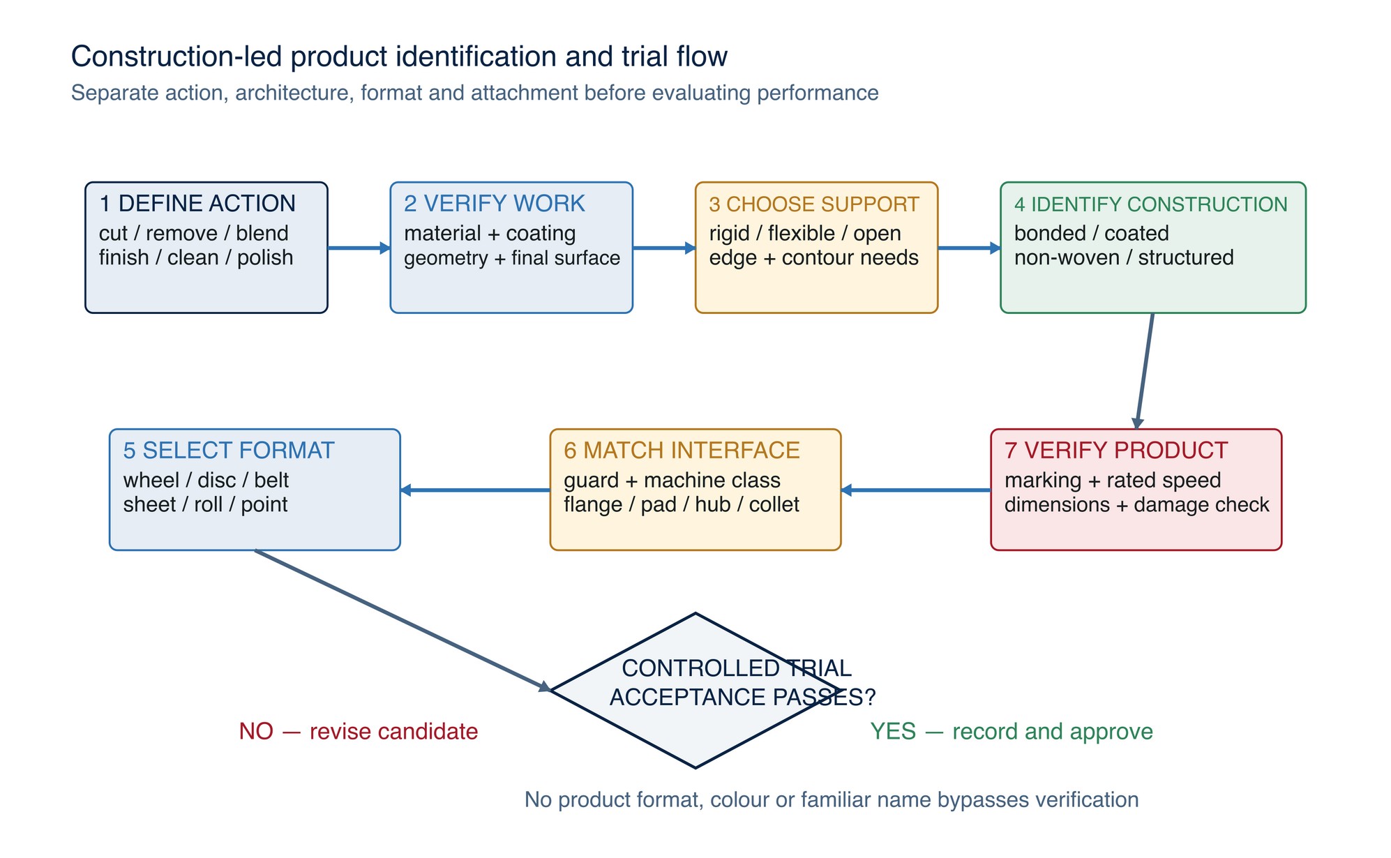
Use the construction questions before comparing brands or prices:
- Define the required action: cutting, stock removal, blending, deburring, scratch refinement, cleaning or polishing.
- Identify the work material, coating, geometry, edge sensitivity and required final surface.
- Choose the needed support: rigid, controlled-flex, backing-pad supported, flap-supported, open-web or structured.
- Verify debris clearance, cooling and contamination controls.
- Match the complete attachment and machine class.
- Confirm dimensions and maximum operating speed from the product marking and manufacturer data.
- Inspect storage condition and physical integrity.
- Trial the candidate on representative material with defined stop and acceptance criteria.
Common construction mistakes
- selecting by colour, diameter or familiar trade name instead of the complete specification;
- treating a product format as a construction family;
- fitting a self-supporting-looking coated disc without its required backing pad;
- using a reinforced cutting wheel for side grinding;
- assuming every non-woven product is soft or every bonded product is rigid;
- ignoring the flap adhesive, backing plate, belt joint, shank or attachment because it is not abrasive;
- continuing after delamination, cupping, cracks, abnormal shedding, exposed support or uneven wear;
- mixing product families across stainless steel and carbon steel without contamination control; and
- replacing a declared proprietary grade with a similar-looking FEPA number.
Construction troubleshooting
| Observed signal | Construction-related possibilities | Controlled response |
|---|---|---|
| Grain sheds unusually fast | Wrong contact, damaged bond, excessive force, incompatible material or product deterioration | Stop; inspect product, machine and work; compare with manufacturer limits |
| Coated disc curls, cups or delaminates | Moisture, heat, storage damage, wrong pad, edge loading or attachment failure | Remove from service; inspect the batch and storage; verify pad and method |
| Flaps separate or backing plate appears early | Snagging, wrong surface or angle, overload, damage or end of usable life | Stop immediately; quarantine damaged product; verify product instructions |
| Non-woven product smears or loads | Incompatible grade or density, trapped debris, heat, contamination or worn web | Stop, clean and reassess construction and process; do not add force blindly |
| Belt tracks poorly or joint strikes | Wrong direction, damaged edge or joint, incorrect tension, machine alignment or width mismatch | Stop; inspect belt and machine; do not repair the joint in production |
| Wheel vibration or runout | Damage, contamination at mounting faces, wrong flange, poor seating, machine fault or wheel imbalance | Stop and isolate; inspect by the approved wheel-mounting procedure |
The table is diagnostic screening, not permission to repair or re-use a damaged abrasive.
Practical example: weld blending on a stainless enclosure
A team needs to remove a weld crown, blend the transition and create a controlled directional pre-finish. A construction-led trial separates three roles:
- Geometry correction: shortlist a product with enough support to remove the crown without collapsing into the adjacent sheet.
- Blend transition: shortlist a controlled-flex coated or flap construction that can spread contact without hiding a remaining ridge.
- Surface refinement: shortlist a clean, segregated coated, structured or non-woven product whose construction can follow the enclosure without destroying the required lay.
For each role, the team records the complete product, attachment, machine, speed limit, construction, trial technique, time, wear, heat indication, geometry and surface result. The lowest purchase price is not automatically the lowest process cost.
A product that loads, sheds, contaminates stainless, requires excess rework or damages edges may have a higher cost per accepted part.
Construction checks before use
Identify the complete product construction and attachment system before comparing formats. Check the declared work material and operation, dimensions, backing or wheel structure, bond, reinforcement, hub or bore, permitted working face, rotation direction where marked, and required pad, flange, collet or contact element.
Inspect storage condition and product integrity before mounting. Never substitute an adapter, support element, belt joint or product format solely because it appears to fit. Refer to the product label, Technical Data Sheet, or MKTECH representative.
Backing Materials and Bond Systems
The heading “Backing Materials and Bond Systems” opens the following chapter of the printed handbook (page 66 onward), outside this chapter extract.