
Production engineers, supervisors, grinding and finishing operators, fabricators, coating personnel, hygienic-design teams, maintenance personnel, QA/QC inspectors, designers, trainers and technical sales personnel
The controlled language and decision framework for surface texture, lay direction, roughness, waviness, gloss, reflectivity, scratch pattern, visual appearance, functional finish, cosmetic finish, cleanability and coating preparation. Chapter 023 develops roughness parameters and visual-finish assessment in more detail. Product selection and exact operating values are confirmed for the identified abrasive, machine and application.
A finish requirement never overrides safe abrasive selection, guarding, extraction, work support, chemical control, contamination control or the current machine and product instructions. Stop before finishing an unidentified material, coating, pressure boundary, food-contact surface, sealing surface, fatigue-critical feature or corrosion-critical surface without its governing specification and rework authority. Control dust, fibres, metals, compounds, solvents and residues under the workplace risk assessment. [S007–S009; S014; S017]
Chapter objectives
After this chapter, the reader should be able to:
- separate surface form, waviness, roughness, lay and local defects;
- explain why a grit designation or one roughness value does not define a complete finish;
- distinguish profile measurement from areal measurement;
- distinguish gloss, reflectivity, haze and visual appearance;
- define functional and cosmetic finish requirements without treating them as opposites;
- recognise how scratch direction and rogue scratches affect inspection and service;
- treat cleanability as a validated surface-and-system requirement;
- separate coating cleanliness from coating profile;
- create a controlled visual-comparison protocol; and
- write a complete finish requirement and representative verification record.
Surface finish is a controlled surface state
“Surface finish” is an umbrella term. It can refer to measured texture, visible appearance, process route or service behaviour. These are related, but they are not interchangeable.
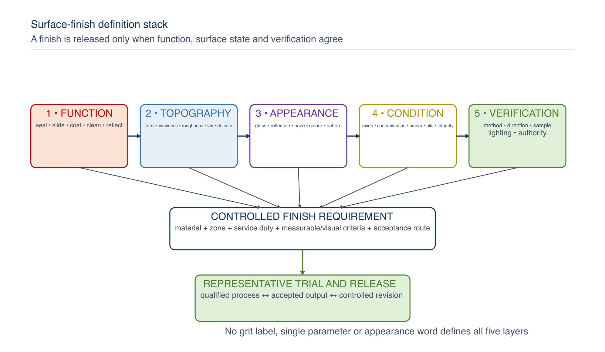
A usable finish definition has five linked parts:
- Function: what the surface must do — seal, slide, retain lubricant, accept coating, resist soiling, drain, clean, bond, reflect, diffuse or provide a chosen appearance.
- Topography: form, waviness, roughness, lay, peaks, valleys and local defects at defined scales.
- Appearance: gloss, reflectivity, haze, image clarity, colour, directional contrast and visible scratch pattern under controlled viewing.
- Condition: contamination, oxide, embedded material, smearing, burr, pits, cracks, heat tint, coating residue and surface integrity.
- Verification: the parameter, instrument, filter, measurement direction, sample, lighting, viewing geometry, locations and acceptance decision.
ISO 21920-1 provides the current published framework for indicating profile surface texture in technical product documentation. ISO 21920-2 defines terms and parameters for profile methods, while ISO 25178-2 covers areal parameters. These standards provide a specification language; they do not select an abrasive process or supply an MKTECH acceptance value. [S086; S105–S106]
Separate form, waviness, roughness, lay and defects
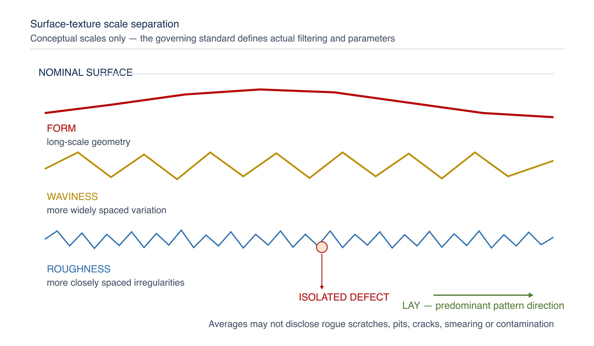
A manufactured surface contains features at different scales. The inspection method must separate the scale of interest from the others.
- Form is the long-scale geometry relative to the nominal shape: flatness, straightness, roundness, taper or other overall deviation.
- Waviness consists of more widely spaced surface variations. Machine vibration, chatter, thermal movement, support behaviour and process rhythm may contribute.
- Roughness consists of the more closely spaced irregularities remaining after the specified separation of longer-scale components.
- Lay is the predominant direction of the surface pattern. Grinding, belt finishing, brushing, turning and blasting can create different directional structures.
- Local defects or features include isolated scratches, pits, cracks, dents, embedded particles, pull-outs and other discontinuities that a statistical roughness value may not represent.
NIST separates roughness, waviness and form and identifies process marks and grinding grit as potential roughness sources, with vibration or chatter as potential waviness sources. The separation is conceptual until the governing filter and measurement procedure are defined. [S105; S107]
Roughness is a filtered measurement, not the whole finish
A roughness result is produced by a defined measurement chain. The chain includes the surface, instrument, sampling, trace direction or measured area, filtering, evaluation length or area, parameter calculation, calibration and uncertainty. Change the chain and the result may change.
Profile methods evaluate a line trace. Areal methods evaluate a surface area. They can reveal different information and their parameter names, filters and evaluation rules must come from the same declared standard and revision. Do not substitute an areal value for a profile requirement, or a profile value for an areal requirement, merely because both use micrometres. [S105–S106]
A complete roughness requirement records:
- standard and revision;
- profile or areal method;
- parameter and units;
- filter or nesting-index/cut-off settings required by the governing method;
- evaluation length or area and number of locations;
- measurement direction relative to lay;
- instrument, tip or optical configuration where material;
- calibration/reference artefact and uncertainty control;
- treatment of edges, curvature, steps, pores and excluded defects; and
- acceptance rule, including how repeated readings are handled.
One number cannot reveal whether the surface contains a deep rogue scratch, periodic banding, directional mismatch, smeared metal or contamination. Two surfaces with a similar average-height result can have different spacing, peak shape, lay, appearance and service behaviour. [S105–S108]
Lay direction and scratch pattern
Lay is not decorative vocabulary. Direction changes how a surface looks, how a stylus crosses features, how a seal or sliding contact interacts with the pattern, how liquid drains or is wiped, and how repair marks become visible.
Define the required direction from a part datum: longitudinal, transverse, circumferential, radial, cross-hatched, multidirectional, non-directional or sample-matched. Identify transitions, corners, weld zones and visible faces. “Brush with the grain” is not enough unless the grain direction is shown or tied to an approved sample.
Scratch pattern must be assessed for:
- dominant direction and permitted angular variation;
- continuity across adjoining panels, welds and repaired areas;
- scratch width, spacing and contrast where specified;
- cross-grain or hook marks;
- isolated deep scratches and start/stop marks;
- banding, overlap lines and edge brightening; and
- consistency at changes of curvature or viewing direction.
The final abrasive grade does not uniquely determine the result. Backing, grain shape, wear state, contact support, pressure, speed, feed, overlap, heat, lubricant and prior scratches all influence the delivered surface. BSSA therefore recommends controlled roughness definitions or agreed reference samples instead of relying on words such as “brushed” or “satin” alone. [S028]
Gloss, reflectivity and visual appearance are different
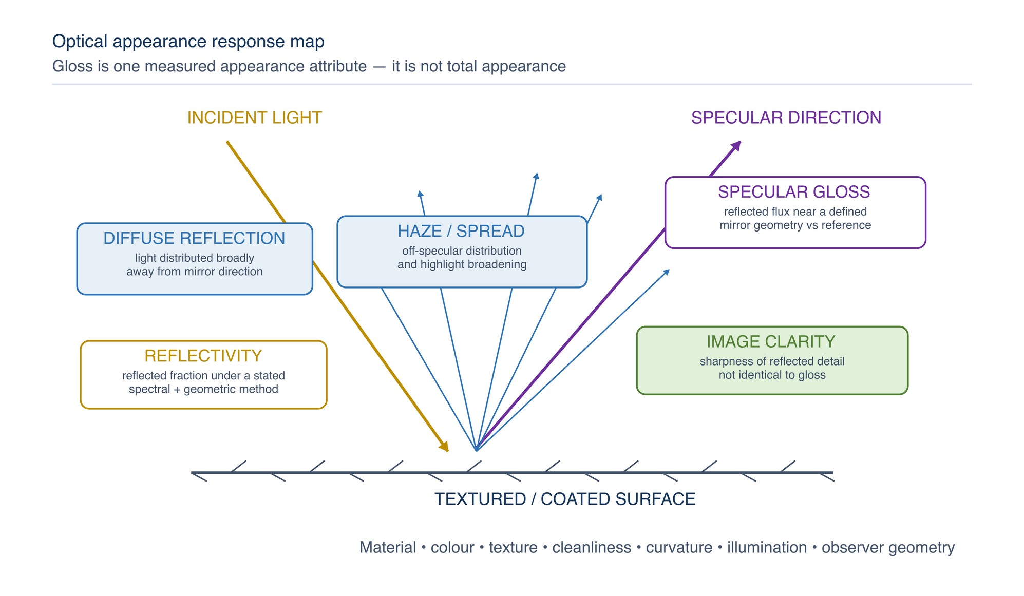
Specular gloss is an appearance attribute associated with light reflected near the mirror direction relative to a reference standard and a defined geometry. Reflectivity describes how much incident light is reflected under a stated spectral and geometric measurement arrangement. Diffuse reflection is light distributed away from the mirror direction. Haze and distinctness of image describe other aspects of how reflected light is spread or how clearly an image is reproduced.
NIST notes that gloss perception changes with the source, sample and observer geometry. ASTM D523-25 also distinguishes specular gloss from distinctness of image, reflection haze and texture. ISO 2813:2014 uses 20°, 60° and 85° geometries for non-textured coatings on plane opaque substrates; that scope does not automatically make the method suitable for bare directional metal, curved work or every polished surface. [S108–S110]
A bright surface is not automatically smooth, and a smooth measured surface is not automatically mirror-like. Directional scratches can produce strong highlights in one orientation and a dull appearance in another. Colour, oxide, coating, cleanliness, curvature, light size, viewing angle and surrounding reflections also change what an observer sees.
Visual appearance requires a controlled protocol
Visual inspection is a measurement activity when appearance is an acceptance requirement. Control the conditions so different reviewers see substantially the same task.
Record:
- part cleanliness and dry/wet condition;
- inspection zone and protected or excluded regions;
- light source, colour quality, intensity range and position;
- viewing distance, angle and observation movement;
- part orientation and lay direction;
- background, surrounding reflections and glare control;
- approved physical sample, master panel or image reference;
- defects to report separately from overall appearance;
- permitted variation between adjacent pieces, batches and repair zones; and
- reviewer, date, photographs and disposition.
Photographs support traceability but do not automatically reproduce appearance. Camera exposure, white balance, focal length, polarisation, compression and screen conditions can hide or exaggerate scratches and gloss. Use photographs under a fixed protocol and retain the physical reference where contractual appearance matters.
Functional and cosmetic finish
A functional finish is controlled because it influences service, manufacturing or inspection. A cosmetic finish is controlled because the visible result is part of the acceptance requirement. These categories can overlap.
| Finish characteristic | Functional question | Appearance question | Verification route |
|---|---|---|---|
| Roughness/topography | Does the surface support sealing, friction, adhesion, drainage or cleaning? | Is the texture visibly uniform? | Declared profile/areal method plus visual review |
| Lay/scratch direction | Does direction affect motion, wiping, drainage or stress concentration? | Does the pattern align across visible faces? | Datum-based direction check and approved sample |
| Waviness/form | Does long-scale deviation affect fit, contact or coating thickness? | Are bands, ripples or oil-canning visible? | Geometry/waviness method plus controlled lighting |
| Gloss/reflection | Is optical response part of sensing, glare or identification? | Is shininess, haze or image clarity consistent? | Applicable optical method plus viewing protocol |
| Surface condition | Are oxide, contamination, pits or embedded particles acceptable? | Are stains, marks or repair zones visible? | Cleanliness/material test plus defect inspection |
| Coating preparation | Is the surface clean and profiled for the coating system? | Is exposed prepared work visually consistent? | Coating specification, cleanliness and profile tests |
| Cleanability | Can the complete system be repeatedly cleaned and verified? | Does the surface appear free of soil after cleaning? | Validated cleaning method; visual check is supplementary |
A cosmetic requirement may be contract-critical even when it does not change mechanical performance. A functional surface may look uneven yet meet its engineered requirement. The drawing, customer specification and validation plan decide; operators must not downgrade either category informally.
Cleanability is a system property
Cleanability depends on more than average roughness. Surface topology, pits, folds, burrs, cracks, joints, weld profile, dead spaces, drainage, material compatibility, soil, temperature, chemistry, time, flow or mechanical action and verification method all interact.
EHEDG guidance and conference material use roughness as one hygienic-design input while emphasising that finishing technology changes topography and that required cleanability must be achieved. A widely quoted numerical value from food-equipment guidance is not a universal rule for every material, process or industry, and it does not override a validated hygienic-design requirement. [S114]
For cleanability-critical work:
- identify the product/soil and microbiological or chemical risk;
- define accessible and inaccessible zones, joints and drain paths;
- prohibit pits, cracks, folds, embedded contamination and unapproved repairs;
- specify material and surface-treatment compatibility;
- define the texture measurement and visual defect controls;
- qualify the cleaning method under representative worst-case conditions; and
- release only after the specified residue, microbiological or process verification passes.
For stainless steel, smoother and cleanly produced finishes can support corrosion performance and reduce dirt retention, but alloy, environment, fabrication, contamination and maintenance remain part of the system. [S028]
Coating preparation: cleanliness and profile are separate
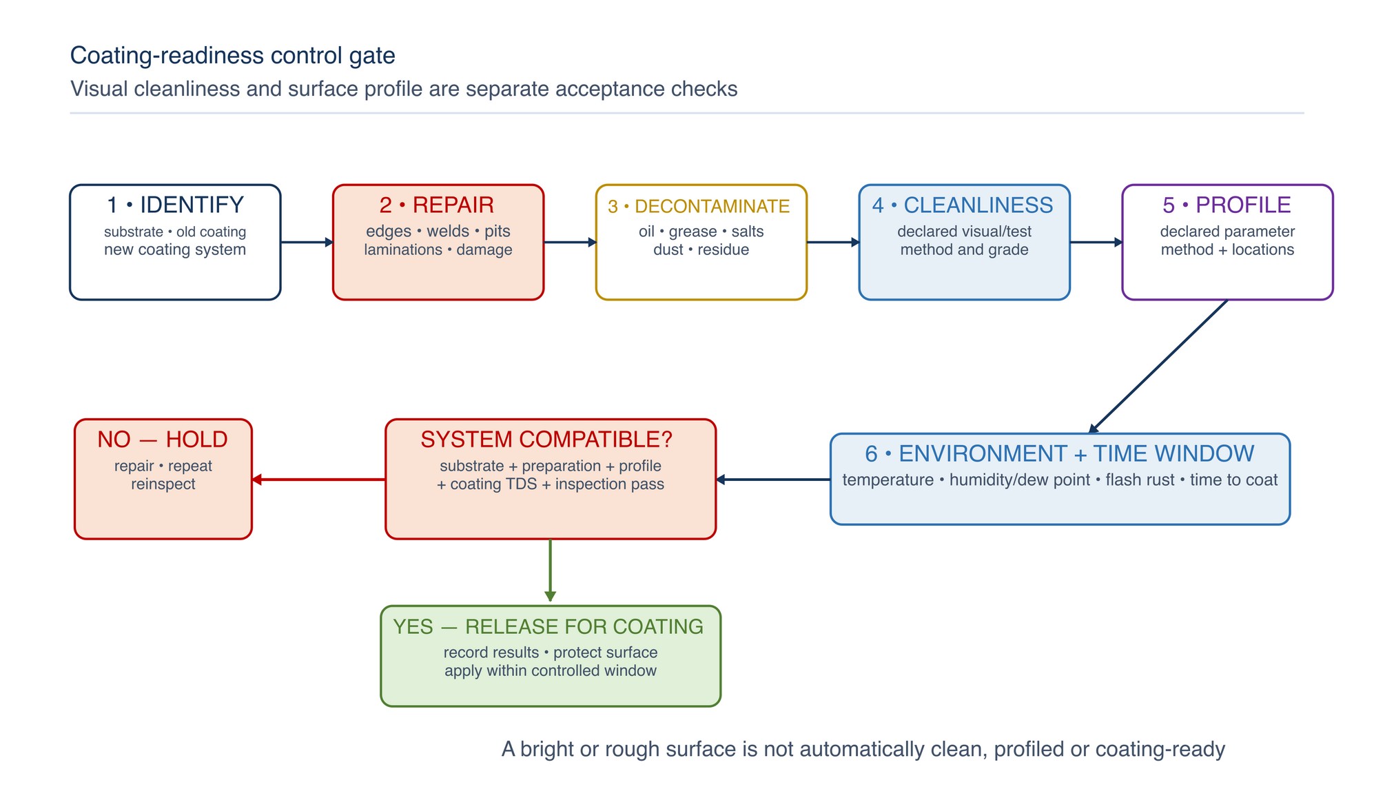
A coating surface must be both suitably clean and suitably prepared for the exact coating system. “Rough enough” does not mean clean. “Bright metal” does not prove that soluble salts, oil, dust, oxide or embedded contamination are within limits.
ISO 8501-1 defines visual rust grades and preparation grades for relevant steel substrates. Its reference photographs and written descriptions assess visual cleanliness; they are not a universal roughness scale. ISO 8503-1 defines comparators for visual and tactile grading of abrasive blast-cleaned steel profile. Its comparators are not generic grinding comparators and do not establish a coating manufacturer’s target profile. ISO 8504-1 sets general surface-preparation principles and reinforces that the method must be selected for the protective-paint system and substrate condition. [S111–S113]
The coating readiness record should identify:
- substrate material, grade, previous coating and initial condition;
- coating system, manufacturer and current technical data;
- required preparation method and cleanliness grade;
- required profile parameter/range and measurement method;
- oil, grease, dust, soluble-salt, moisture and environmental controls;
- edges, welds, pits, laminations and repair areas;
- time between preparation and coating and any flash-rust limit;
- calibrated inspection equipment and locations; and
- hold, repair and release authority.
Translate vague finish words into controlled requirements
Terms such as “satin,” “brushed,” “polished,” “mirror,” “grain,” “smooth,” “clean,” “low glare” and “No. 4” are useful for initial communication but incomplete for production release.
Translate the requested word into:
- material, product form and visible/service faces;
- functional and cosmetic duties;
- reference standard and revision;
- texture parameter(s), method and direction;
- required lay and scratch-pattern rules;
- gloss, reflection or colour method if applicable;
- surface-condition and contamination limits;
- coating or cleanability requirements;
- physical master/reference sample and controlled viewing conditions;
- representative trial and repair method; and
- acceptance locations, frequency and named approver.
Do not promise that a named abrasive grit will reproduce a previous finish across different suppliers, backing types, wear states, machines, operators or geometries. The qualified process and its accepted output are the controlled pair.
Representative finish trial and record
Before repeat production, trial the exact proposed material, geometry, starting condition, abrasive sequence, machine, support, compound, cleaning method and inspection system. Include edges, welds, curves, transitions and repair zones that represent the production difficulty.
The record should contain:
- drawing/customer finish requirement and service duty;
- material, heat/lot, coating and starting surface;
- finish zones, datum and lay direction;
- each abrasive/product identity, sequence and revision-controlled instruction;
- machine, support/interface, extraction and contamination controls;
- texture instrument, standard, parameter, filter, direction and locations;
- lighting, viewing geometry, reference sample and photographs;
- cleanliness, coating-preparation or cleanability tests where applicable;
- dimensional, surface-integrity and downstream checks;
- nonconformities, permitted repair and reinspection;
- approved reference panel or retained part; and
- engineering, quality, customer and production release as required.
Applying a finish requirement
Translate the finish description into a usable specification: material and starting condition, functional purpose, lay direction, roughness or gloss parameter where relevant, permitted local defects, master panel or visual reference, lighting and viewing method, inspection locations, cleaning condition and repair boundaries.
Choose the abrasive sequence only after the required surface state is defined. Confirm the result on representative material that includes the difficult geometry—edges, welds, curves, transitions and repair zones. Refer to the product label, Technical Data Sheet, or MKTECH representative.
Surface Roughness and Visual Finish
The next chapter, Surface Roughness and Visual Finish, begins on the following page of the printed handbook (page 178), outside this chapter extract.