
Production engineers, supervisors, grinding and finishing operators, fabricators, quality personnel, designers, inspectors, trainers and technical sales personnel
Practical interpretation and control of Ra, Rz and Rt; measurement direction and method; directional and random texture; mill, satin, brushed, No. 4, bright and mirror finish language; comparison, visual inspection and acceptance. This handbook is an educational and application-selection guide. Follow the current machine instructions. Refer to the product label, Technical Data Sheet, or MKTECH representative.
Surface inspection does not make an unsafe process acceptable. Current machine and abrasive instructions, speed compatibility, guarding, work support, extraction, contamination control, chemical control and workplace risk assessment remain mandatory. Stop if the material, coating, required service, permissible stock removal, finish zone, defect authority or governing specification is unidentified. Never continue polishing merely to chase appearance when doing so could reduce thickness, change geometry, damage a coating or pressure boundary, embed contamination or overheat the work. [S007–S009; S014; S017]
Chapter objectives
After this chapter, the reader should be able to:
- explain what Ra, Rz and Rt reveal and what they do not reveal;
- recognise why the standard, revision and measurement operator must accompany a roughness value;
- define measurement direction relative to lay;
- separate roughness, local defects and visual appearance;
- distinguish directional and random texture;
- interpret mill, satin, brushed, No. 4, bright and mirror as controlled finish descriptions;
- avoid unsupported grit-to-roughness conversions and false cross-standard equivalence;
- establish a representative master-panel and viewing protocol; and
- create a complete surface-finish inspection and release record.
Roughness parameters are evidence, not finish names
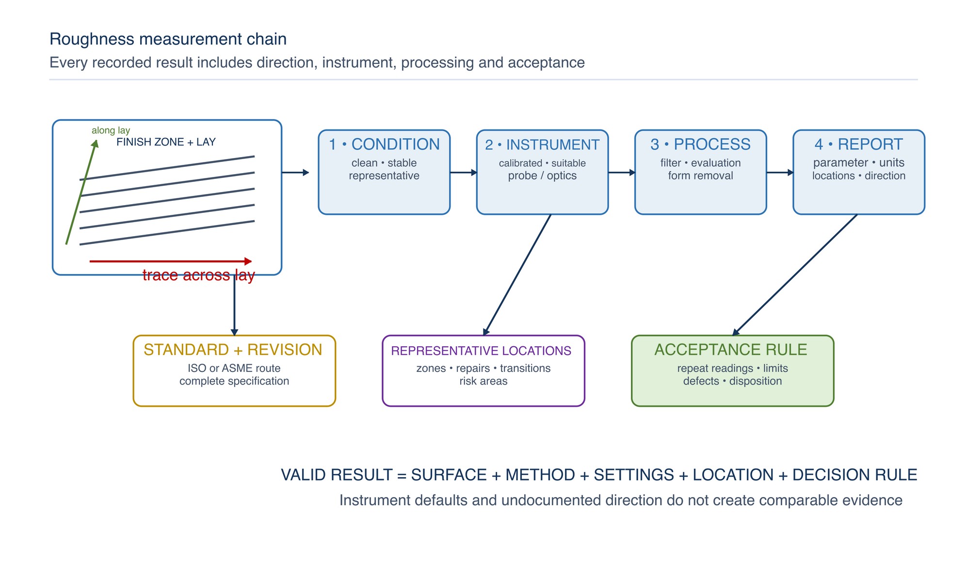
Ra, Rz and Rt are profile-height parameters produced by a defined measurement chain. They are not abrasive grades, scratch directions, gloss levels, defect limits or complete finish descriptions. A result has meaning only with the governing standard and revision, units, filter or nesting-index settings, sampling and evaluation conditions, direction, instrument configuration, locations and acceptance rule.
The current published ISO profile route is ISO 21920: Part 1 for indication, Part 2 for terms and parameters and Part 3 for the complete specification operator. ISO 4287 and ISO 4288 have been withdrawn. A legacy drawing that cites either withdrawn standard must still be interpreted under the cited revision or formally changed; it must not be silently converted to ISO 21920. ASME B46.1-2019, reaffirmed in 2026, is a separate current surface-texture route. Do not mix ISO and ASME parameter meanings, filters, symbols or acceptance logic in one requirement. [S086; S105; S115–S116]
The practical rule is simple: write the whole measurement requirement, not just “Ra 0.8” or “Rz 6.3.” A unitless roughness value is incomplete, and a parameter named without its standard can be ambiguous.
Ra — useful average, incomplete picture
Ra expresses the arithmetic-average magnitude of profile height deviations over the declared evaluation. It is widely used because it condenses many profile points into one stable summary. It is useful for process monitoring and drawing requirements when the method is controlled.
Ra does not disclose:
- whether the profile contains rounded plateaus or sharp peaks;
- whether valleys are shallow and frequent or isolated and deep;
- the spacing or periodicity of the texture;
- the direction of lay;
- waviness or form that the chosen filtering removes;
- a rogue scratch, pit, crack, burr, embedded particle or smear outside the statistical response; or
- gloss, reflectivity, haze, image clarity or colour.
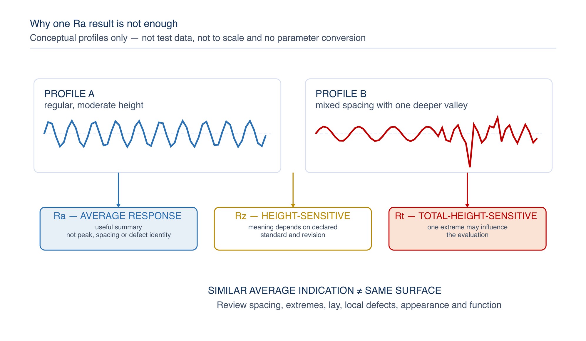
Two surfaces can produce a similar Ra indication while differing materially in peak/valley structure, spacing, direction, appearance and service behaviour. Therefore Ra must be supplemented when sealing, sliding, fatigue, coating, cleanability, optical appearance or defect sensitivity requires more information. [S105–S107; S117]
Rz — state the standard and revision
Rz gives more emphasis to profile peak-to-valley height than Ra, but the exact definition and evaluation have varied among ISO, ASME, JIS and legacy usage. Some instruments and old reports also expose legacy variants under similar names. “Rz” alone is therefore not a complete requirement.
Under the current chosen system, Rz can help reveal a surface whose height range is more severe than its average suggests. It can support control of deeper valleys or higher peaks, but it still depends on filtering, sampling, trace location and the specified evaluation. It does not identify the cause of an extreme or guarantee detection of every isolated defect.
Whenever Rz is specified or reported, record:
- the standard and revision that defines it;
- whether an instrument setting represents a legacy or regional variant;
- the profile filter and evaluation conditions;
- trace direction and measurement locations;
- repeated-reading and acceptance rules; and
- any separate defect inspection.
Do not convert Ra to Rz using a fixed multiplier. The relationship changes with process, profile shape, spacing, material, abrasive condition and measurement method. [S105–S107; S116–S117]
Rt — total profile height within the evaluation
Rt represents the total height spanned by the roughness profile over the declared evaluation length under the chosen standard and filtering. Because one high peak or deep valley can influence the result, Rt can be useful as a warning indicator for extremes that an average may soften.
That sensitivity is also a limitation. Rt may change because of a real local feature, contamination on the surface, a trace crossing an edge or pore, poor levelling, vibration, instrument condition or an unrepresentative location. It must be interpreted with the profile trace and visual/defect evidence, not used alone to condemn or release a surface.
Ra, Rz and Rt are complementary, not interchangeable. A functional specification may need one, two or all three—or a different profile/areal parameter altogether—based on the engineering duty. Parameter selection must follow the governing specification and function, not convenience. [S105; S116–S117]
Control the complete measurement chain
A reliable roughness result starts before the probe touches the part.
- Identify the requirement. Confirm drawing, customer specification, standard, revision, parameter, units, limit, acceptance rule and finish zone.
- Stabilise the surface. Clean using an approved non-damaging method; define whether the part is dry, coated or otherwise conditioned. Do not polish the inspection area during cleaning.
- Select the method. Confirm contact stylus or optical method, instrument range, tip or optical configuration, calibration/reference artefact and environmental suitability.
- Define separation and evaluation. Apply the governing filter, nesting index or cut-off, sampling/evaluation length or area and form-removal rule. Do not accept an instrument’s default without checking it.
- Define direction. State the trace relative to the predominant lay and part datum. On directional surfaces, across-lay measurement often exposes height variation more strongly, but the drawing or method controls.
- Select representative locations. Include process zones, repairs, weld transitions, curvature and risk areas while avoiding edges or features only where the method permits.
- Measure without corrupting the trace. Prevent rocking, skid errors, vibration, tip contamination, excessive stylus force, unsuitable traverse speed or optical artefacts.
- Review the profile and context. Check for outliers, edge crossings, non-measured length, levelling error and disagreement with the visible surface.
- Apply the acceptance rule. Use the required number of readings and stated treatment of repeated results; do not average away a prohibited defect.
- Preserve traceability. Record raw traces or native data where practical, settings, calibration status, operator, date, locations, photographs and disposition.
NIST calibration work demonstrates that measurement conditions and uncertainty sources are part of a credible result. Manufacturer guidance likewise identifies probe, speed, calibration and direction as practical controls, but the instrument maker does not replace the governing standard or customer specification. [S117; S121]
Directional and random texture
A directional finish has a predominant visible or measured lay. Grinding, belt finishing and brushing commonly produce aligned marks. Define direction from a part datum: longitudinal, transverse, circumferential, radial or another drawing-controlled orientation. Control continuity across panels, welds, repairs, corners and curved surfaces.
A random or non-directional finish has no intentionally dominant macroscopic direction under the specified viewing or measurement method. It still has microtexture and can show local swirls, clouds, overlap marks or directional patches. “Random” does not mean uncontrolled.
For either type, specify:
- visible and functional zones;
- required direction or permitted lack of direction;
- reference sample or measured texture requirement;
- lighting and viewing orientation;
- prohibited cross-grain, hook, swirl, start/stop and repair marks;
- transition rules at welds, edges and adjoining panels; and
- separate roughness and defect acceptance.
Trace direction can change the measured result on an anisotropic surface. When direction is not stated, reports from different operators may not be comparable. Record the direction relative to lay for every controlled trace. [S028; S105; S120 –S121]
Finish families and controlled terminology
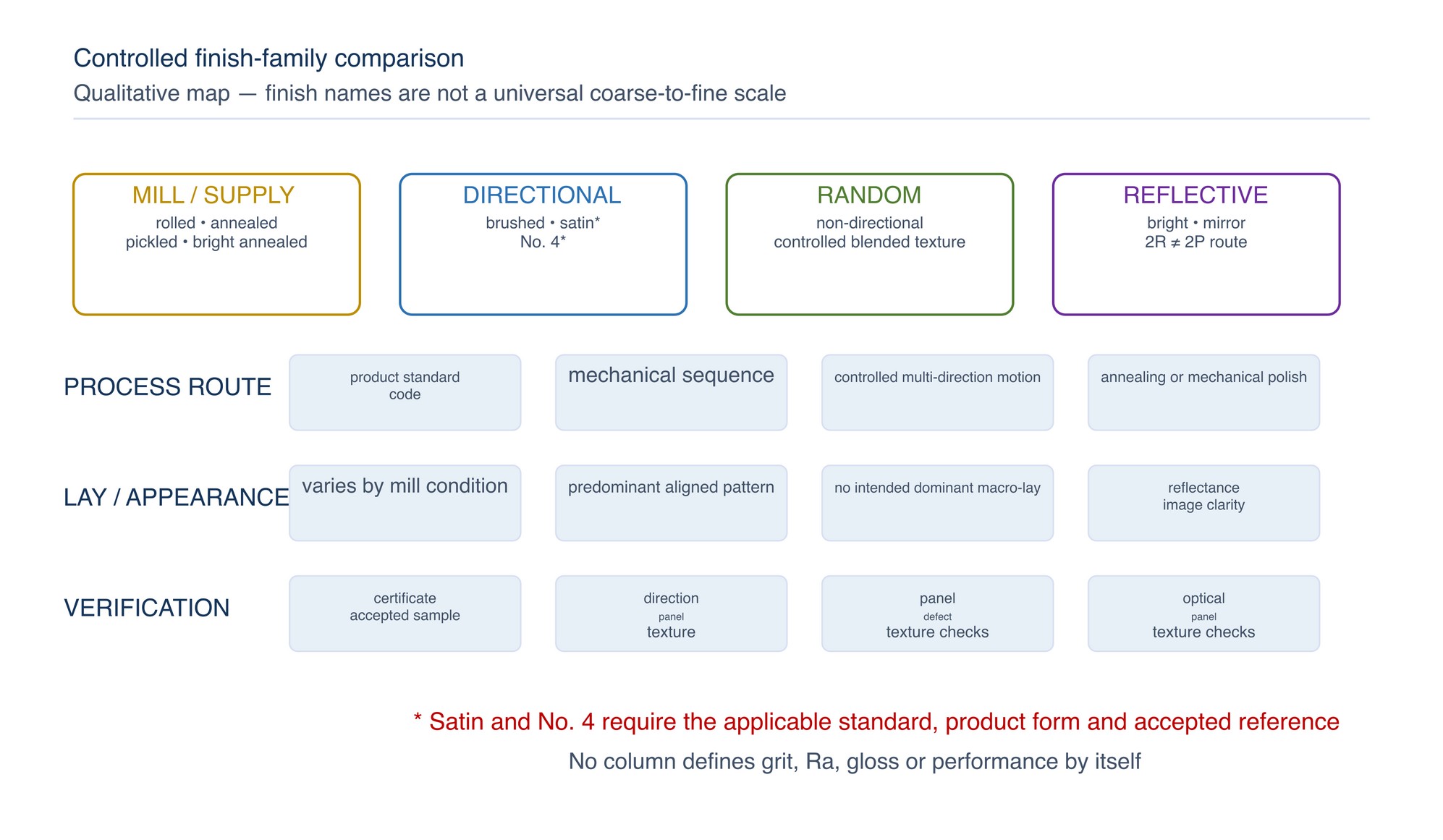
Finish names usually describe a process family, appearance, lay or supply condition. They do not automatically establish Ra, Rz, Rt, gloss or a grit sequence.
| Finish term | Typical controlled meaning | Acceptance method | Critical warning |
|---|---|---|---|
| Directional | Predominant lay tied to a part datum | Direction map, master panel, roughness traces in stated direction, defect limits | Direction alone does not define roughness or gloss |
| Random / non-directional | No intended dominant macroscopic lay under stated viewing | Master panel, viewing protocol, texture/defect checks | Not a synonym for uncontrolled or defect-free |
| Mill finish | Surface supplied by a defined manufacturing route such as hot/cold rolling, annealing, pickling or bright annealing | Material/product standard, finish code, supplier certificate and accepted sample | Not simply “unfinished” and not one Ra value |
| Brushed | Intentionally directional mechanical texture | Declared system, direction, sample, texture and appearance limits | Contractor and supplier terms vary; final grit alone is insufficient |
| Satin | Low-to-moderate sheen appearance, often with controlled fine texture | Named standard/supplier system, master panel, optical/texture checks where required | May be directional or differently processed; not a universal roughness band |
| No. 4 | ASTM flat-product polished-finish designation where ASTM A480/A480M applies | Exact standard/revision, product form, supplier sample, pattern and acceptance record | Not a universal name for all metals, forms or vendors |
| Bright | High-reflectance appearance from a named route, which may include bright annealing or mechanical polishing | Process designation, reflectance/gloss/image requirements and master panel | Bright-annealed 2R and mechanically polished 2P are not the same process |
| Mirror | Highly reflective finish with controlled image clarity and low visible disturbance | Named finish system, master panel, optical protocol, texture and defect limits | “Mirror” is not one grit, one Ra value or guaranteed optical performance |
The table is a control chart, not a conversion table. BSSA and worldstainless show useful indicative relationships among ASTM and EN stainless flat-product finish families—for example No. 4 with 2J, satin-related No. 6 with 2K and mirror-related No. 8 with 2P—but explicitly treat such mappings as contextual rather than exact equivalence. [S028; S118–S120]
Mill finish is a specified supply condition
Mill finish describes a surface resulting from a controlled manufacturing route. Stainless flat products may be hot rolled, annealed, pickled, cold rolled, skin passed or bright annealed under named codes. Different mill finishes can therefore be scale-bearing, matte, smooth, reflective or prepared for later polishing.
Specify the applicable product standard, finish code, product form, thickness range, visible face, protective film condition and permitted defects. Retain supplier certificates and accepted samples where appearance is contractual. Do not assume that mill finish from different mills, coils, batches or thicknesses will be visually identical merely because the same broad word appears on an order. [S119–S120]
Brushed, satin and No. 4 finishes
Brushed commonly describes a directional mechanical finish. The delivered pattern depends on the starting surface, abrasive construction and grading system, machine, support, speed, pressure, feed, overlap, wear, lubrication, cleaning and operator control. The last grit designation cannot define the result by itself.
Satin commonly communicates a subdued sheen with a controlled texture, but its process and direction vary. In stainless flat-product contexts, EN 2K and ASTM No. 6 may be used as related satin-family references, while supplier and contractor language can differ.
No. 4 is meaningful only when tied to the applicable ASTM A480/A480M flat-product context and a controlled supplier/customer interpretation. It is often associated with a general-purpose directional polished appearance and may be related indicatively to EN 2J, but neither relationship establishes a universal grit, Ra or appearance.
For production, replace the isolated word with a complete requirement: material and product form, starting condition, applicable finish designation and revision, direction, master panel, roughness method and limits if needed, viewing protocol, permitted variation, local-defect limits, repair route and approver. [S028; S118–S120]
Bright and mirror finishes
Bright finish may describe high reflectance produced by different routes. Bright-annealed stainless flat product, commonly designated 2R in EN practice, obtains its surface through controlled annealing conditions and rolling history. A mechanically bright-polished surface follows another route. Similar visual brightness does not make the metallurgy, texture or repair response equivalent.
Mirror finish usually communicates high reflectivity and strong image clarity with very low visible disturbance. In stainless flat-product references, mechanically bright polished 2P and ASTM No. 8 are often treated as related mirror-family designations. This is an indicative crosswalk, not automatic equivalence.
A mirror requirement should define image clarity, haze/distortion, directional trace, waviness, orange peel, pinholes, pits, edge condition, weld and repair zones, colour, cleanliness and viewing geometry. Ra alone cannot release a mirror surface: long-scale waviness or fine directional marks may distort reflected images even when average roughness is low. [S108; S119–S120]
There is no universal grit-to-Ra conversion
Abrasive grit indicates a particle-size distribution within a named grading system; it does not state the depth of the delivered scratch or the final Ra. The workpiece material and starting surface, grain type and shape, coated/bonded/non-woven construction, backing and support, pressure, speed, feed, overlap, lubrication, loading, wear state, heat, prior defects and measurement method all affect the outcome. [S028; S039–S043]
Published grit-to-Ra tables can be useful only when they represent the same controlled material, abrasive product, process, machine and measurement method. They are trial data, not universal physics. Do not use a supplier’s typical finish number as a universal acceptance limit outside the conditions in which it was established.
A defensible local relationship is developed by:
- defining material, geometry, starting condition and finish duty;
- identifying complete abrasive and machine systems;
- controlling settings, contact support, wear state, sequence and cleaning;
- producing representative coupons and difficult production features;
- measuring under a declared standard and method;
- assessing visual pattern, local defects and downstream function;
- establishing variation across operators, lots and consumable life;
- retaining accepted master panels and raw measurement data; and
- approving a revision-controlled process window and change rule.
Visual comparison requires a physical control system
A finish photograph is useful evidence but is not automatically a master. Camera exposure, focal length, white balance, sharpening, compression, screen brightness, part curvature and reflected surroundings can change the apparent finish.
For appearance-critical work, create a physical master-panel system:
- use the same material, product form and representative geometry;
- identify master, limit and defect samples separately;
- assign a unique ID, revision, owner and approval date;
- mark viewing orientation and lay direction without damaging the comparison face;
- define light source, position, distance, angle, background and inspection movement;
- define cleanliness, handling, gloves, storage and protective packaging;
- prohibit touching or reworking the comparison face;
- record photographs under fixed camera conditions for traceability;
- inspect master condition periodically and replace only through controlled approval; and
- keep obsolete panels segregated but traceable.
Visual inspection should separately record overall match, lay/pattern continuity, local defects, repair visibility and adjacent-part consistency. A part can match the overall sheen yet fail because of a deep rogue scratch; conversely, a measured roughness result can pass while the visible direction or image clarity fails.
Controlled inspection and release
Release requires both the specified quantitative and visual evidence. Neither route should be used to override the other.
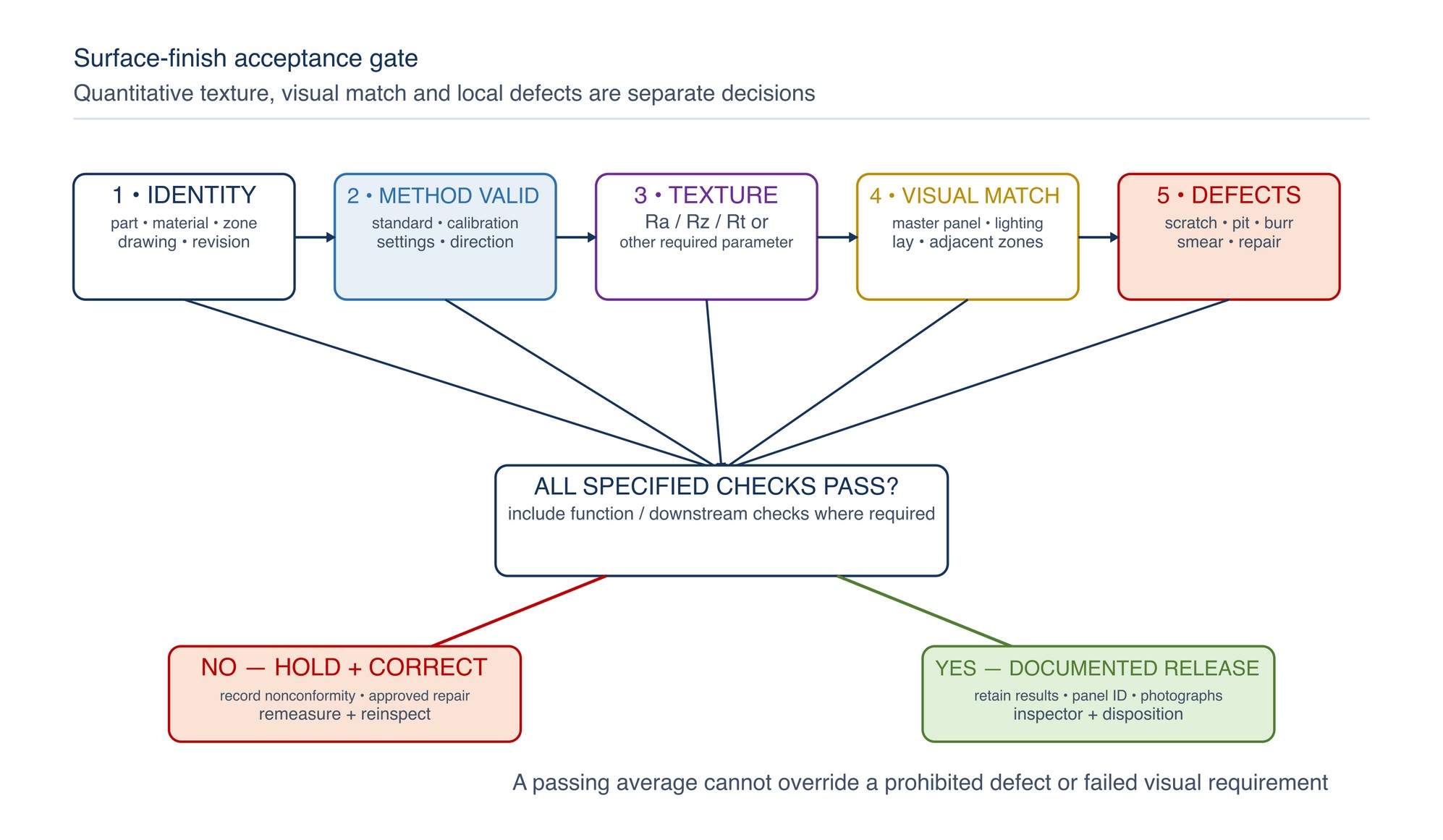
The inspection record should include:
- part, material, product form, batch/heat and drawing revision;
- finish zone, datum, service duty and applicable standard/revision;
- required parameter(s), units, filters, evaluation and acceptance rule;
- instrument, probe/optical configuration, calibration and uncertainty control;
- measurement direction, locations, repeated results and native data references;
- finish name and process designation without treating either as a measured value;
- master-panel ID/revision and controlled viewing conditions;
- overall appearance, lay, local defects, welds, edges, transitions and repair zones;
- photographs tied to the controlled camera/viewing protocol;
- dimensional, contamination, coating, cleanability or service checks where required;
- nonconformity, permitted repair, remeasurement and reinspection; and
- inspector, date and named engineering, quality, customer or production disposition.
If the standard, measurement settings, trace direction, master panel or acceptance authority is unclear, place the work on hold until the requirement is defined. Do not reverse-engineer acceptance from a single historical reading or an internet finish photograph.
Applying the guidance
Use the following sequence when selecting and controlling a finishing process:
- define the material, product form, starting condition and required function;
- translate the requested appearance into a named standard or accepted physical sample;
- identify the required lay, roughness parameter, defect limits and viewing conditions;
- select an abrasive product and machine that are suitable for the material, geometry and finish stage;
- verify maximum operating speed, intended use and accessories against the product label, current Technical Data Sheet and machine instructions;
- establish the sequence on representative work using controlled technique and inspection;
- compare measured texture, visual appearance and local defects with the specified acceptance criteria; and
- record the process and inspection conditions needed for repeatable production.
When a drawing or customer requirement specifies Ra, Rz, Rt, No. 4, satin, bright or mirror, confirm the referenced standard, revision and acceptance method before production. For abrasive selection or product-specific application advice, consult the current product documentation or an MKTECH representative.
Scratch Refinement and Grit Progression
Scratch Refinement and Grit Progression is the next chapter of the printed handbook and appears on page 186, outside this chapter extract.