
Production engineers, supervisors, operators, QA/QC personnel, maintenance teams, safety personnel, procurement staff and technical sales personnel
Practical scratch identification, abrasive-stage selection, cross-sanding, directional refinement, inspection lighting, contrast-marker methods, edge protection and final finish matching for industrial metalwork.
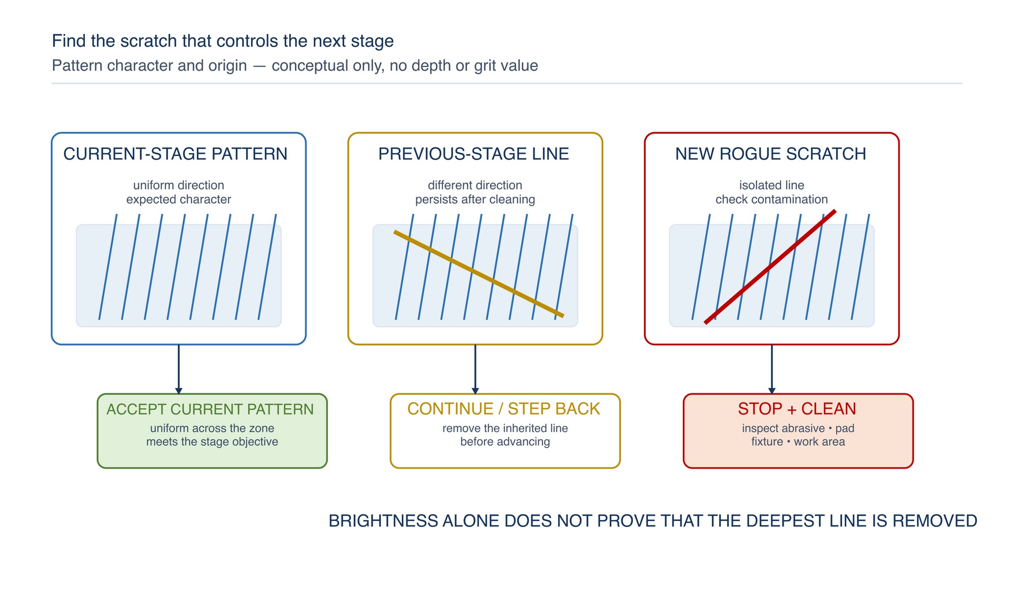
A refinement stage is complete only when the unwanted scratches from the previous stage have been removed across the controlled area. A brighter surface is not proof that the deepest scratch has gone.
- Use only abrasive products intended for the material, machine, mounting and task.
- Confirm that the abrasive and every accessory are compatible with the machine speed and dimensions.
- Keep guards, handles, extraction and other protective systems in place as required.
- Secure the workpiece and maintain a stable stance and controlled line of fire.
- Wear eye and face, hearing, respiratory, hand, body and foot protection selected from the workplace risk assessment.
- Control sparks, hot particles, combustible materials and mixed-metal dust. Aluminium and other combustible metal dusts require specific collection and fire/explosion controls.
- Stop for vibration, damaged backing, torn belts, abnormal sound, loading that creates rogue scratches, excessive heat or unstable support.
- Keep hands, clothing, hair and cables away from abrasive contact and in-running nip points.
Refer to the product label, Technical Data Sheet, or MKTECH representative.
Chapter objectives
After this chapter, the reader should be able to:
- find and classify the deepest unacceptable scratch before selecting an abrasive;
- choose a practical next stage without relying on a universal grit-jump rule;
- use changed sanding direction, controlled lighting and suitable contrast methods to expose residual scratches;
- protect edges, features, thin sections and adjacent finished faces during refinement;
- re-establish a straight, consistent final lay where a directional finish is required;
- distinguish incomplete refinement from contamination, loading, smearing and local overworking; and
- confirm the finished surface against the specified visual, dimensional and measured requirements.
Refinement is controlled scratch replacement
Every abrasive stage creates a new surface while removing part of the old one. The practical objective is to replace the unwanted pattern with a more uniform pattern that the next stage can remove efficiently. This continues until the required functional or visual finish is achieved.
Grit designation alone cannot predict the delivered scratch. The result also depends on abrasive mineral and shape, grading system, coating or bond, backing, contact support, machine motion, speed, pressure, feed, overlap, wear, loading, lubrication, workpiece material, geometry and contamination. FEPA identifies P-grades for coated abrasives and explains that abrasive particle size is controlled as a distribution rather than a single diameter. The complete abrasive product and process therefore matter as much as the number on the backing. [S039–S041]
The central production rule is simple:
- define the unacceptable scratch or starting texture;
- select the least aggressive suitable stage that can remove it without unnecessary damage;
- create a uniform new pattern;
- clean and inspect the whole controlled area; and
- advance only when the previous pattern is no longer present above the acceptance criterion.
Struers applies the same principle in systematic materialographic preparation: each successive stage removes damage from the preceding stage, the surface is examined between stages, and contamination is controlled. Its setting is laboratory preparation, but the scratch-removal logic transfers directly to industrial refinement. [S123]
Define the target before touching the surface
Start with the finish requirement, not the abrasive shelf. Confirm:
- material and product form;
- visible face, functional face and non-critical zones;
- starting condition, coating, oxide, weld transition or damage;
- required lay direction or non-directional appearance;
- accepted reference panel, drawing note, roughness requirement or coating specification;
- local defect limits and dimensional allowance;
- edge, radius, corner, hole, thread and adjoining-surface protection;
- contamination controls, especially for stainless steel and non-ferrous work; and
- the required cleaning and inspection method.
A final finish name such as brushed, satin, No. 4 or mirror does not by itself define a universal grit sequence. Material condition, product construction and process route influence the appearance, while a physical master panel or declared measurement method provides the acceptance reference. [S028; S119–S120]
Identify the deepest unacceptable scratch
The deepest visible line governs the early refinement work. If it remains, finer stages may brighten the surrounding peaks while leaving the valley untouched. The defect can then reappear under final lighting, polishing or coating.
Use a disciplined inspection sequence:
- Stop the machine and make the work area safe.
- Clean the surface using a method suitable for the material and downstream process.
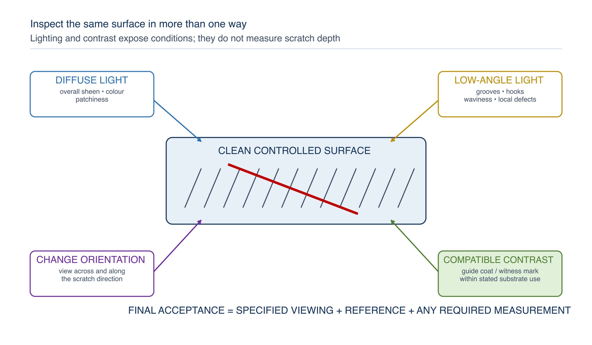
- Inspect the dry surface under broad diffuse light to see overall uniformity.
- Add a low-angle line or point light and move it across the surface.
- Rotate either the part, the light or the viewing position so scratches are viewed both across and along their direction.
- Use suitable magnification for small defects, while retaining a normal viewing check for overall appearance.
- Mark the defect beside the controlled area or use an approved contrasting aid that will not damage or contaminate the surface.
- Check edges, low spots, curves, weld toes, corners and transitions separately.
Classify what you see:
- Previous-stage scratch: direction or character differs from the current uniform pattern and persists after cleaning.
- Current-stage scratch: matches the intended new pattern and is reasonably uniform across the worked area.
- Rogue scratch: isolated line introduced by loose grit, swarf, a damaged abrasive, contaminated support or debris trapped at the interface.
- Smear or bright patch: displaced or rubbed material that can hide a valley rather than remove it.
- Geometric defect: groove, undercut, flat spot, rolled edge or low area that cannot be corrected by surface refinement alone without checking dimensions.
Visual appearance and measured profile reveal different aspects of a surface. Use visual inspection to locate and classify the defect; use the specified measurement method where depth, roughness or function is controlled. [S042; S105; S117]
Choose the starting stage and the next stage
Begin with the least aggressive abrasive stage that removes the identified defect efficiently while protecting material allowance, edges and heat-sensitive geometry. Starting too fine can waste time and consumables; starting too coarse creates deeper damage that must later be removed.
Select the next stage by capability, not by a memorised number:
- identify the grading system and full product construction;
- consider the work material, hardness, ductility and tendency to load or smear;
- match the product form and support to the surface geometry;
- assess whether the next stage can reach the bottom of the deepest remaining scratch;
- consider the permitted heat, dimensional change and edge condition; and
- confirm that the stage can be inspected clearly before moving on.
Manufacturer sequences can provide a useful starting point when they apply to the same material, product family and machine system. They are not universal conversion charts. A change from coated abrasive to structured abrasive, non-woven product, film or polishing compound can alter the grading language and cutting behaviour even when the labels appear numerically related. [S039–S041; S046; S060]
| Starting condition | Practical first decision | Checks before advancing | Avoid |
|---|---|---|---|
| Isolated deep scratch on an otherwise acceptable face | Localise the defect, protect surrounding finish and use the least aggressive suitable corrective stage | Deep line removed without a hollow, halo or edge change | Chasing the line with a tipped disc or prolonged local dwell |
| Uniform coarse pattern | Use a complete intermediate stage across the full controlled zone under changed lighting | Old-direction or coarse-character scratches are absent | Polishing only the peaks until the surface looks bright |
| Random deep lines after an otherwise uniform pass | Stop, clean, inspect abrasive, pad, support and work area for contamination or damage | New test pass produces a uniform pattern without rogue lines | Continuing with the same contaminated or loaded interface |
| Soft or ductile material showing shine and drag marks | Restore cutting action with a suitable product and controlled contact | Cleanly generated, uniform texture replaces smear | Adding pressure to a loaded or blunt abrasive |
| Thin sheet, edge or formed feature | Use controlled support and short, distributed contact | Scratch is removed while shape, edge and temperature remain acceptable | Concentrated force, unsupported work or repeated dwell at the edge |
| Directional finish repair | Plan a blend zone and final lay from a fixed datum | Direction, spacing, sheen and transition match the approved reference | A small bright patch with hooks, cross-lines or abrupt boundaries |
Cross-sanding makes old scratches easier to see
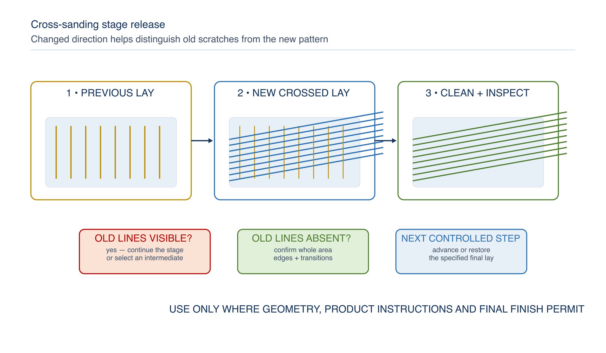
Where geometry, product instructions and the required final finish permit, change the working direction between stages. When the new stage crosses the previous lay, residual old scratches remain visually distinct. The surface is ready to advance only when the old-direction lines have disappeared across the full controlled zone.
The direction change need not be exactly the same for every job. A clear angular separation is useful, but access, curvature, machine motion, final lay and safe tool control govern the actual path. On random-orbital or non-directional processes, the old and new patterns may not separate cleanly; use cleaning, controlled lighting, contrast aids and close inspection instead.
Cross-sanding is an inspection method, not the required final appearance. When the specification calls for a directional finish, the final stage must re-establish the specified lay from the defined part datum. Do not leave cross-lines hidden beneath temporary shine.
Directional sanding and final lay
A directional finish should read as one continuous surface. Establish the direction from a feature that operators and inspectors can repeat: longitudinal, transverse, circumferential, radial or another drawing-controlled datum.
Practical controls include:
- align the tool or belt before contact;
- use stable support and maintain the intended contact footprint;
- travel in a consistent path with controlled overlap;
- avoid stopping, reversing or pivoting while the abrasive is cutting in the visible zone;
- feather into and out of a repair so the transition is gradual;
- work with the grain during final matching;
- carry the lay consistently across weld blends and adjoining panels; and
- inspect line straightness, hooks, swirls, start/stop marks and local sheen from several angles.
Directional stainless finishing is normally separated into weld levelling, grain setting and final finishing. Straight-line tools can help restore a directional pattern; inspect a small area from several angles and ease contact at the ends of strokes when feathering a repair. Apply staged refinement, grain control and gradual blending without transferring product-specific settings. [S122]
Clean between every stage
Loose abrasive particles, swarf and loaded debris can create a scratch deeper than the nominal stage. Clean the workpiece, abrasive interface, support pad, fixture and nearby work area before changing grade or product family.
Use a cleaning method compatible with the material and next process. A clean, dedicated brush, suitable vacuum extraction or approved wipe may be appropriate. Avoid sweeping a contaminated cloth across the acceptance face. Compressed air can introduce oil or water and can project particles; use it only where the workplace method, air quality and exposure controls permit.
Keep abrasive products segregated by grade and material service. Do not place a clean fine abrasive on a contaminated bench or reuse a pad carrying coarse particles. For stainless steel, maintain dedicated tools and consumables where cross-contamination from carbon steel would impair corrosion performance or appearance.
Marker and guide-coat methods
A contrast aid can make scratches, low spots and incomplete coverage easier to see. Use it as an inspection aid, not as the acceptance standard.
Suitable methods include:
- a temporary mark placed beside an isolated defect rather than across the acceptance face;
- a light, compatible contrasting medium applied to a sacrificial or subsequently removed surface layer;
- a manufacturer-approved dry guide coat on the fillers or primers listed in its Technical Data Sheet; and
- removable witness marks on masking or adjacent non-finish areas to show the planned blend boundary.
A compatible contrast guide coat can reveal scratches and pinholes in declared filler and primer applications during wet or dry sanding. That use does not automatically authorise the same material on bare metal, hygienic surfaces, corrosion-sensitive alloys or a surface going directly to coating. Confirm substrate compatibility, residue removal and downstream-process acceptance before use. [S124]
Do not use an unidentified permanent marker, dye, aerosol, chalk, adhesive or solvent on a controlled finish. A marker can stain porous material, introduce residue, affect coating adhesion or create false contrast. Remove the aid as required, clean the surface and perform the final inspection without relying on residual colour.
Inspection lighting and viewing discipline
One light angle can hide a defect that another angle reveals. Use a repeatable combination:
- diffuse overhead light for overall patchiness, colour and sheen;
- low-angle line light for grooves, waviness, hooks and local high or low areas;
- changed viewing direction to expose scratches parallel to the first line of sight; and
- normal-use viewing for the customer-facing appearance of the finished part.
Keep the surface clean and dry unless the acceptance method specifies another condition. Reflections from windows, clothing and nearby equipment can alter apparent sheen. Compare the workpiece and the approved reference under the same light, angle, distance, orientation and cleanliness condition. Photographs support traceability but do not replace the physical comparison where appearance is critical. [S108; S119–S120]
Protect edges, corners and adjacent faces
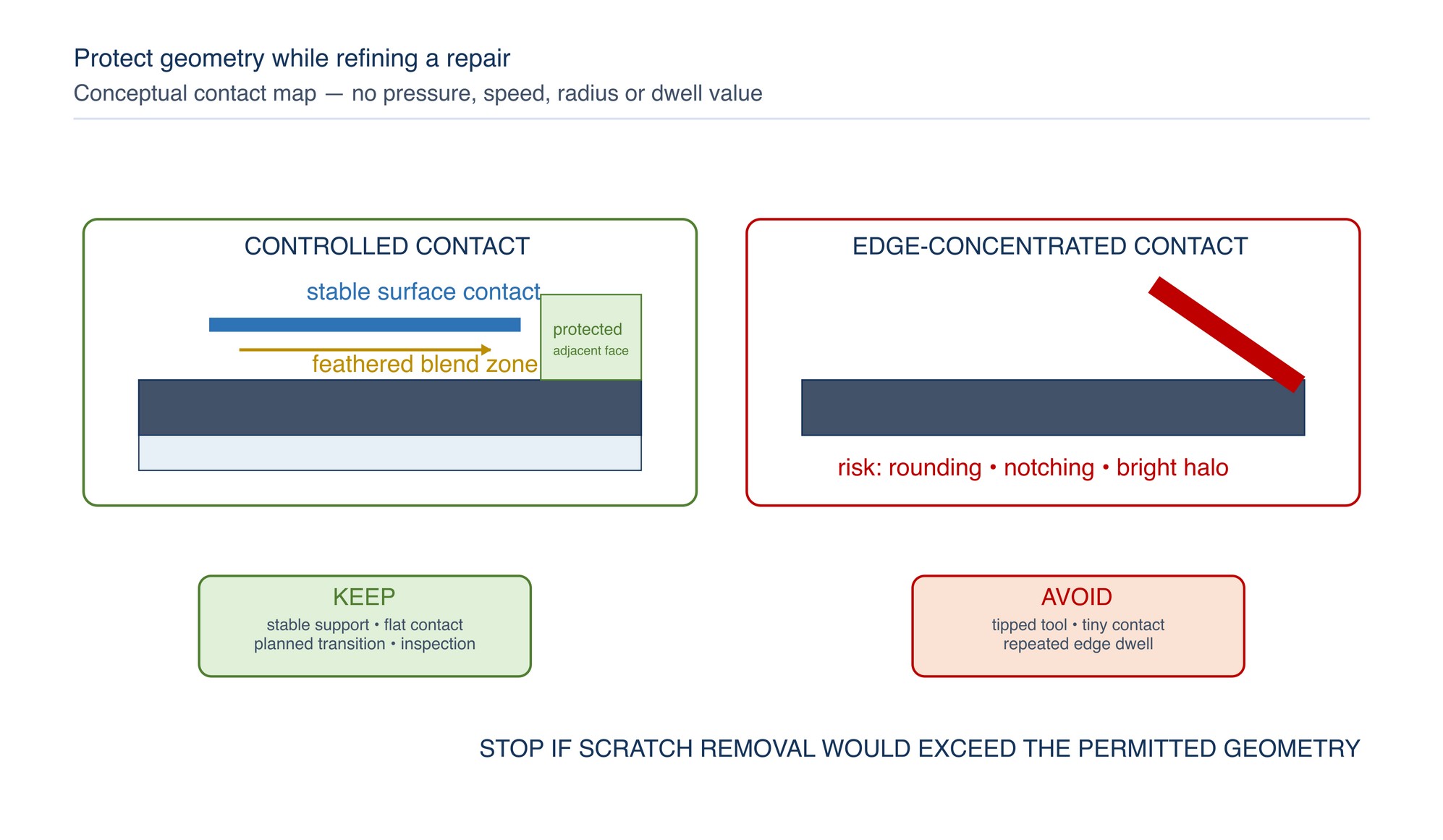
Edges concentrate contact pressure and are easy to round, thin, notch or over-brighten. Flexible or resilient products may wrap over an edge and remove material from both the face and side. Struers identifies resilient polishing surfaces, excessive time and force as contributors to edge rounding in materialographic preparation. The industrial response is to control support, contact, dwell and inspection rather than repeatedly chasing the edge. [S123]
Use these practical controls:
- mask or shield an adjacent finished face with a material suitable for the process;
- use a stable backing or contact support appropriate to the abrasive and geometry;
- keep the tool flat and avoid tipping the abrasive onto a small contact point;
- reduce repeated dwell at an edge and distribute corrective work over a planned blend zone;
- finish faces and edges in a deliberate order so one operation does not damage the other;
- inspect radius, chamfer, wall thickness, flatness and edge line where function requires it; and
- stop when scratch removal would exceed the permitted dimensional or geometric allowance.
On thin sheet and formed sections, also control heat and support. Surface appearance does not justify distortion, loss of section or a changed functional edge.
Match the final finish
Final matching requires more than reaching the same last grit. Match the attributes the customer actually sees or the component function requires:
- lay direction and straightness;
- scratch spacing and uniformity;
- sheen, reflectivity and colour;
- transition into the surrounding surface;
- local defects, halos, swirls and repair boundaries;
- edge and feature condition; and
- specified roughness or other measured requirement.
Whenever possible, refine a repair over a planned blend zone rather than polishing a tiny isolated patch. Extend the transition gradually while protecting unaffected areas. Use the same material condition, abrasive construction, machine motion, contact support and controlled technique that produced the accepted reference. A final grit label alone does not reproduce the result.
Compare the part with an approved master panel or accepted production reference under controlled viewing. If the specification includes Ra, Rz, Rt, coating readiness, cleanability or another function, perform that check separately; visual agreement cannot replace it. [S105; S117; S119–S120]
Troubleshooting scratch-refinement defects
| Symptom | Likely process cause | Practical correction |
|---|---|---|
| Deep line remains after a finer stage | Previous stage incomplete; grit jump too ambitious; valley deeper than surrounding pattern | Return to the last effective stage or add a suitable intermediate stage, then re-refine the full controlled zone |
| New isolated deep lines appear | Loose grit, swarf, loaded abrasive, damaged pad, contaminated bench or wrong consumable segregation | Stop, clean, inspect and replace contaminated or damaged interface components before repeating |
| Surface becomes bright but old lines remain | Peaks are being rubbed or polished while deep valleys remain | Restore effective cutting with a suitable stage; do not add force to a blunt or loaded product |
| Hooks, swirls or stop marks | Tool pivots, stops or reverses while cutting; unstable contact or poor entry/exit control | Re-establish stable motion and finish with the required lay outside or through the affected zone |
| Patch or halo around a repair | Repair area too small; abrupt pressure change; product or wear state differs from surrounding process | Widen the blend zone gradually and match contact, product condition and final direction |
| Edge becomes rounded or over-bright | Abrasive wraps over edge; contact area too small; repeated dwell or excessive force | Improve support, protect adjacent faces, shorten edge exposure and inspect geometry more frequently |
| Finish varies from panel to panel | Direction, overlap, abrasive wear, support, cleaning, lighting or starting surface is inconsistent | Standardise the complete process and compare each panel under the same viewing conditions |
| Fine stage loads or smears | Material is ductile; abrasive is worn or unsuitable; debris is trapped; lubrication or extraction is unsuitable | Clean the interface, replace worn product and select a construction intended for the material and process |
Concise safety reminders
- Use only abrasive products intended for the material, machine, mounting and task.
- Confirm that the abrasive and every accessory are compatible with the machine speed and dimensions.
- Keep guards, handles, extraction and other protective systems in place as required.
- Secure the workpiece and maintain a stable stance and controlled line of fire.
- Wear eye and face, hearing, respiratory, hand, body and foot protection selected from the workplace risk assessment.
- Control sparks, hot particles, combustible materials and mixed-metal dust. Aluminium and other combustible metal dusts require specific collection and fire/explosion controls.
- Stop for vibration, damaged backing, torn belts, abnormal sound, loading that creates rogue scratches, excessive heat or unstable support.
- Keep hands, clothing, hair and cables away from abrasive contact and in-running nip points.
Refer to the product label, Technical Data Sheet, or MKTECH representative.
Application sequence
- Define the finish, controlled zone, lay, dimensional allowance and acceptance method.
- Clean and inspect under diffuse and low-angle light.
- Identify and mark the deepest unacceptable scratch without contaminating the finish.
- Select the least aggressive suitable corrective stage.
- Create a uniform new pattern using stable contact and controlled movement.
- Clean the surface, abrasive interface and work area.
- Inspect from more than one light and viewing direction.
- Change sanding direction between stages where safe and compatible with the required finish.
- Protect edges and adjacent faces, and monitor geometry and heat.
- Re-establish the specified final lay and feather the blend zone.
- Compare with the accepted reference and complete any specified measurement.
- Release the finish only when pattern, appearance, geometry, cleanliness and functional checks all pass.
Directional and Brushed Finishes
The Directional and Brushed Finishes chapter continues on the following page of the printed handbook (page 195), outside this chapter extract.