
Production engineers, supervisors, operators, QA/QC personnel, fabricators, polishers, maintenance teams, safety personnel, procurement staff and technical sales personnel
A practical method for diagnosing and correcting scratches, haze, swirl marks, compound marks, overheating, orange peel, uneven gloss, contamination, edge rounding and visible weld shadow on polished stainless-steel components.
Inspect abrasives, wheels, compounds, machine, guards, mounting, work support and extraction before use. Confirm compatibility and never exceed the lowest marked operating limit in the assembled system. Stop immediately if vibration, irregular running, product damage, rapid heating, smoke or unexpected discolouration develops. Control grinding dust, polishing debris, wheel fibres, compound particles and cleaning vapour at source. [S152; S153; S160]
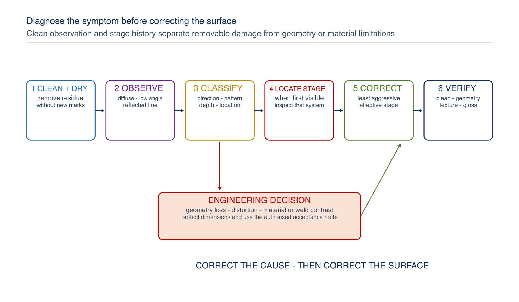
Do not polish a symptom blindly. Clean and inspect the surface, identify whether the defect is inherited, introduced, process-driven or limited by geometry or material condition, then return only to the stage capable of correcting it.
Polishing defects often become most visible at the end of the route, but many originate much earlier. Final buffing can brighten a surface without removing deep scratches, restoring lost geometry or eliminating inherent weld contrast. Effective correction therefore begins with diagnosis rather than additional dwell.
Chapter objectives
After this chapter, the reader should be able to:
- classify the ten common defect families by appearance and likely stage of origin;
- distinguish residue and temporary film from damage in the metal surface;
- select the earliest effective corrective stage without repeating the complete route unnecessarily;
- recognise when further polishing will worsen heat, orange peel, rounding or local distortion;
- diagnose visible weld shadow as geometry, texture, colour or material contrast;
- verify a correction under controlled viewing conditions; and
- prevent recurrence through clean media, stable technique and stage-by-stage inspection.
Diagnose before correcting
Start with a clean, dry and safely supported component. Remove loose dust and compatible compound residue without introducing new scratches. Inspect the same area under diffuse light, low-angle directional light and a reflected straight line or grid. Rotate the part or light so a true surface feature remains attached to the surface while temporary glare changes with the viewing direction. [S161; S163]
Mark the boundaries of the defect using a surface-compatible method away from the finished face. Observe its shape, direction, depth, width, repetition and relationship to the tool path, weld, edge, fixture or handling route. A defect that follows the previous abrasive direction is diagnosed differently from a circular swirl, isolated deep line, broad cloudy patch or reflected wave.
Establish the first process stage at which the feature appeared. If it was not observed earlier, inspect the media, compound, cleaning materials and work area used immediately before discovery. Struers emphasises that identifying when an artefact first occurs is central to correcting the method rather than repeating it. [S168]
Classify the ten visible symptoms
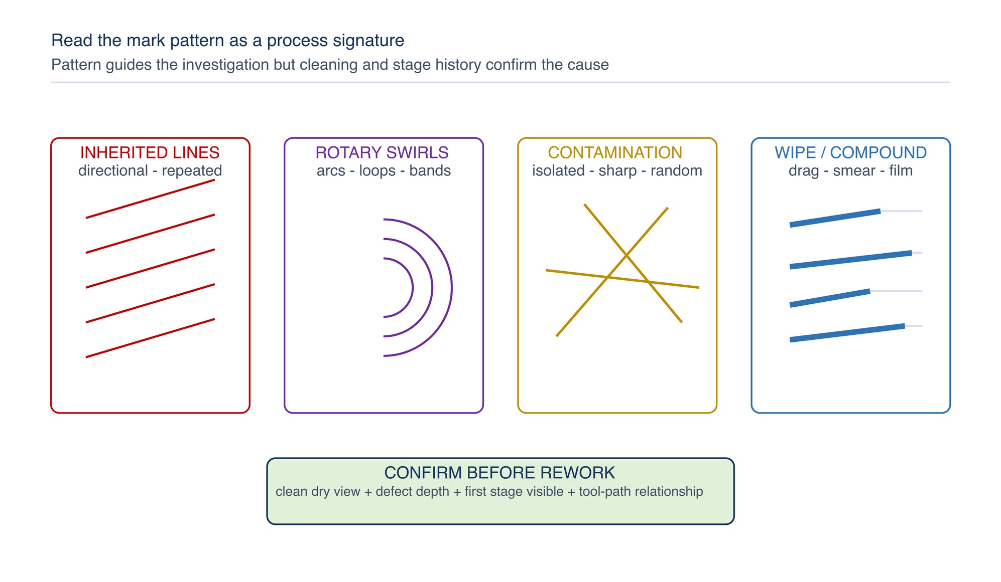
Use the visible symptom as a starting point, not a verdict. Several causes can produce a similar appearance, and one cause can create more than one symptom. Cleanliness, defect direction, reflected geometry and the stage where the mark first appeared provide the strongest initial separation.
| Visible symptom | Typical appearance | Confirming observation | First corrective direction |
|---|---|---|---|
| Remaining scratches | Straight or directional lines deeper than the final pattern | Persist after cleaning and align with an earlier stage | Return to the stage capable of removing their depth |
| Haze | Cloudy or frosted area with reduced image clarity | Remains under diffuse light after residue removal | Separate fine scratch field from film, heat or material texture |
| Swirl marks | Circular arcs, loops or hologram-like bands | Move in emphasis as the light angle changes and follow rotary travel | Correct the polishing pair, path and cleanliness |
| Compound marks | Smears, drag lines, patches or dark deposits | Change or lift during compatible cleaning | Stabilise compound delivery, heat and cleaning |
| Local overheating | Tint, smearing, baked residue, waviness or local dullness | Concentrated at dwell zones, edges or restricted access | Stop, cool and correct the complete contact system |
| Orange peel | Random smooth hills and valleys across a broad area | Shiny surface lacks smooth reflected geometry | Stop fine polishing and re-establish a controlled surface |
| Uneven gloss | Alternating bright and dull zones | Pattern follows coverage, wheel condition or starting finish | Standardise the entering surface and process path |
| Contamination | Isolated deep scratch, embedded speck, dark streak or rust bloom | Reappears after cleaning or traces to dirty media or fixtures | Isolate the source, clean and restore the affected surface |
| Edge rounding | Softened corner, changed radius or reflection roll-over | Silhouette and reflected line depart from the intended edge | Restore geometry only within dimensional allowance |
| Visible weld shadow | Halo, line, wave, colour or texture contrast at the weld | Remains centred on the weld after uniform polishing | Separate profile, texture, oxide and inherent weld contrast |
Correct remaining scratches from their true depth
A remaining scratch is a groove that has not been removed by the later process. It may be an inherited grinding line, a skipped-stage line, an isolated contaminant scratch or a new handling mark. ASSDA notes that the next stage should not begin until scratches from the previous stage have been removed; final buffing removes little material and can round deep lines without eliminating them. [S162; S163]
Clean the area and inspect across the scratch. If a fingernail or stylus check is appropriate to the part and workplace method, use it only away from a critical accepted face and without creating another mark. More reliably, compare the line under low-angle light and magnification. A broad rounded furrow often indicates an old coarse line carried through later stages. A narrow sharp line appearing late often points to contamination or handling.
Return to the least aggressive earlier stage that can remove the scratch efficiently across a sufficiently broad blend zone. Do not polish only the line into a narrow bright trench. Re-establish one uniform scratch family, clean, inspect and then progress again through the controlled sequence.
Separate haze from temporary film
Haze is reduced image clarity over a patch or broad zone. It can arise from unresolved fine scratches, swirl marks, inconsistent pre-polish, local rubbing, dried compound, cleaner residue or a surface texture that polishing cannot level uniformly. Uddeholm describes haze as lower-gloss areas with a silvery frosted appearance; ASSDA warns that brilliant reflectance does not necessarily produce a sharp image. [S167; S163]
First remove residue using a compatible non-scratching method. Inspect the dry surface under diffuse and low-angle light. If the haze disappears, correct cleaning, compound quantity or residue control. If a fine directional pattern remains, return to the stage that can remove it. If the surface is bright but reflected lines remain blurred or wavy, examine profile, orange peel or material response rather than applying more final buff.
Do not judge haze while fresh compound is still filling fine lines. In polishing systems, film can temporarily mask scratches or swirls and allow cloudiness to reappear after cleaning. [S169]
Read swirl marks as a path signature
Swirl marks are fine arcs, loops or hologram-like bands created by the interaction of a rotating tool, polishing medium, travel path and surface. They differ from random contamination scratches because they repeat a recognisable movement pattern. Their visibility often changes strongly with light angle.
Check whether the swirl appeared after compound polishing or final buffing. Inspect the wheel or pad for embedded particles, dried compound, uneven wear, hard seams, damaged edges or cross-use between stages. Confirm the work was clean before the stage and that the tool remained stable rather than tilted onto a narrow contact zone.
Correct swirls with a clean, dedicated and compatible final-polishing system that has enough controlled cut to remove the mark rather than merely fill it. Standardise overlap and coverage; avoid repeated local chasing. Where the swirl is deeper than the final system can remove, return to the preceding cutting-compound or fine-abrasive stage. [S169; S164]
Remove compound marks without creating cleaner marks
Compound marks include smears, dark streaks, drag lines, clumps in recesses and patchy carrier film. They can result from excessive application, poor distribution, rising heat, dried material, an overloaded wheel, inaccessible seams or unsuitable cleaning media. Compound colour alone does not identify its cutting function or compatibility.
Remove the residue with a method compatible with the stainless grade, compound, next operation and service condition. Use clean non-scratching wipes or brushes and change them before they redeposit abrasive particles. Clean seams, holes, fixture-contact areas and edges, then dry and inspect under low-angle light. [S125; S165]
| Check after cleaning | If the mark changes | If the mark remains | Corrective meaning |
|---|---|---|---|
| Gentle compatible wipe | Smear transfers or lightens | Fixed line remains | Residue versus surface scratch |
| Diffuse-light inspection | Cloudiness clears | Broad haze remains | Film versus fine texture |
| Low-angle light | Wipe marks disappear | Furrows or swirls remain | Cleaning trace versus polishing defect |
| Clean-cloth repeat | Cloth stays clean | Residue continues to transfer | Surface ready versus trapped compound |
| Recess inspection | Deposit lifts from seam | Dark line remains in metal | Compound pocket versus contamination or pit |
| Dry-time recheck | Gloss remains stable | Haze returns | Stable finish versus filled scratch field |
Stop local overheating before correction
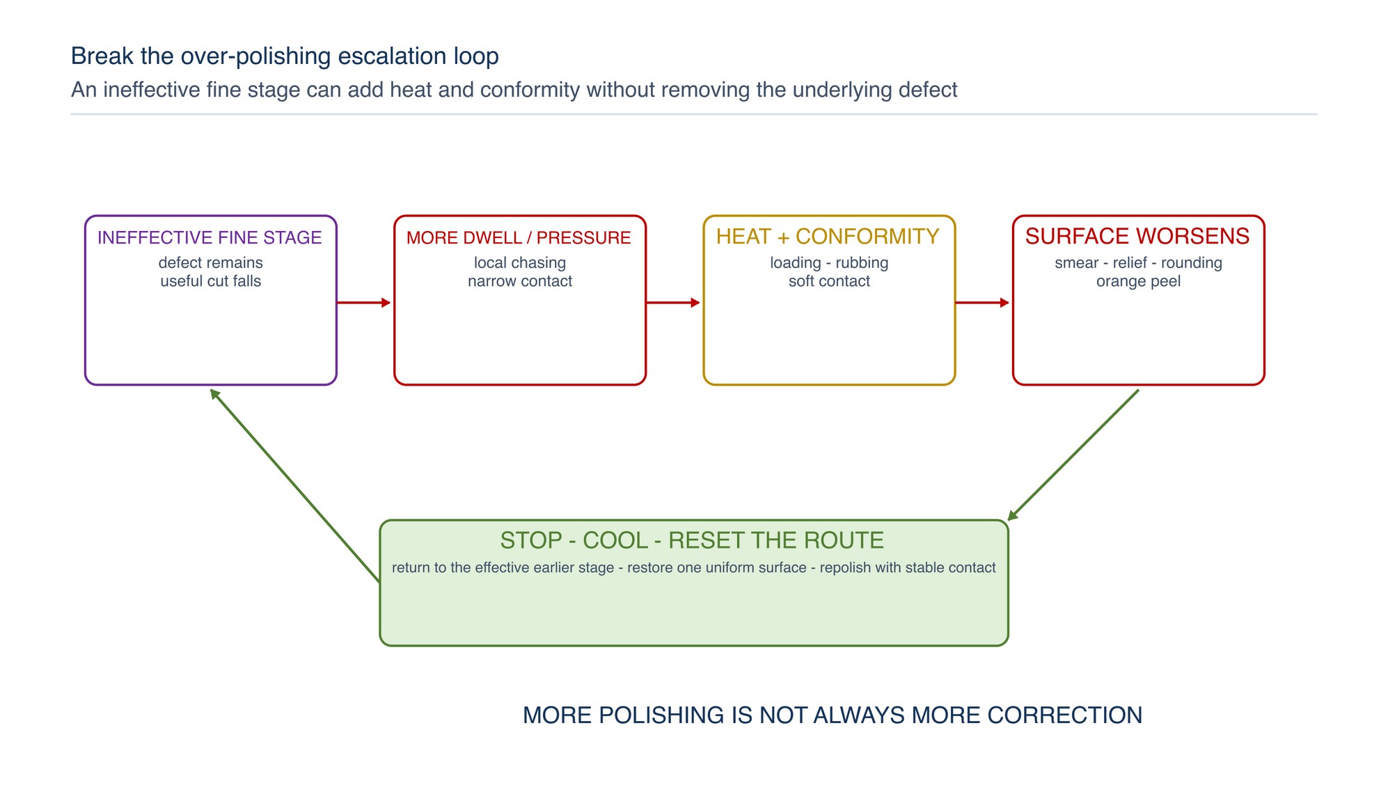
Local overheating can show as heat tint, smearing, baked compound, rapid loading, a dull or bright patch, waviness or distortion. Thin sheet, edges, small contact zones and restricted areas are especially sensitive. Heat that rises while useful cut falls is a process warning, not a reason to press harder.
Stop and allow the part and tool to cool safely. Inspect abrasive or wheel loading, glaze, compound delivery, support firmness, contact width, pressure, travel, dwell, extraction and access. Replace damaged or contaminated consumables and restore effective cutting action before resuming. [S151; S154]
Visible weld heat tint is an oxide condition and may require restoration appropriate to the stainless grade and service. Mechanical brightening alone is not assumed to satisfy every post-weld corrosion requirement. [S166]
Treat orange peel as a stop condition
Orange peel is a broad irregular texture of smooth hills and valleys. The surface may be shiny yet fail to reflect straight lines cleanly. It is different from isolated pits and from large-scale distortion, although the three can coexist.
Process-induced orange peel is associated with over-polishing, particularly prolonged fine polishing, excessive local pressure and a change from a firmer cutting stage to a very soft conformable tool. Uddeholm advises stopping when orange peel appears because additional pressure and dwell can worsen the surface. The defective layer is re-established with the last effective pre-polishing or grinding stage and then repolished with a shorter, cleaner and more stable route. [S167]
Material hardness, grain structure, inclusions, casting condition, heavy cold work or weld microstructure can also limit the uniformity achievable. ASSDA notes that large or variable microstructures, including some welds, may not produce clear image formation or uniform lustre. [S163]
Restore uneven gloss from the entering surface
Uneven gloss appears as adjacent bright and dull zones, bands or patches. Common system causes include a non-uniform starting scratch pattern, inconsistent overlap, changing contact pressure, variable compound delivery, wheel wear, contamination, poor access, part temperature or inspection under changing light.
Clean and inspect the complete area rather than the brightest patch. Compare each zone with the same reference under the same lighting, distance and orientation. If the zones retain different scratch families, return to the earliest stage required to make the entering surface uniform. If the scratch field is uniform but gloss varies, inspect the compound–wheel pair, wheel condition, path and cleaning.
Blend across a controlled zone so the correction does not create a visible island. On large flats, support and travel must prevent local waviness that can appear as gloss variation even when the microtexture is similar.
Remove contamination at its source
Contamination may produce isolated scratches, embedded specks, black streaks, rust bloom, residue or recurring marks after cleaning. Coarse abrasive carried into a fine stage is a common source of deep late scratches. Carbon-steel contact can introduce iron contamination that later rusts and stains the stainless surface. [S161; S165]
Quarantine the suspect abrasive, wheel, compound, fixture, brush, wipe and handling aid. Clean the machine, guards, rests and surrounding area before introducing fresh fine-stage media. Keep stainless-steel tools and cleaning materials segregated where iron contamination matters.
If staining or embedded contamination is suspected, use a restoration method compatible with the finish and service condition. Do not repeatedly buff a rust bloom until its source is known. Chemical cleaning, pickling or passivation must follow the applicable product information, workplace controls and surface-finish requirements because some treatments can alter a mirror appearance. [S125; S166]
Protect edges from rounding and roll-over
Edge rounding occurs when a compliant abrasive or polishing wheel wraps around an edge and removes material from the face and side. Excess dwell, pressure, repeated local contact, a soft support and narrow blend zones accelerate the effect. Struers identifies resilient polishing surfaces and unnecessarily long polishing times as contributors to edge rounding in prepared metal specimens. [S168]
Inspect the silhouette and a reflected straight line across the edge. A glossy edge can still be dimensionally wrong. Once metal has been removed, further polishing cannot restore the original corner. Re-establish geometry only where the drawing, tolerance and remaining material allow it; otherwise route the component for the appropriate disposition.
Prevent recurrence with firmer support, protected transitions, planned travel off the edge, shorter contact and a blend width that does not concentrate work at the corner.
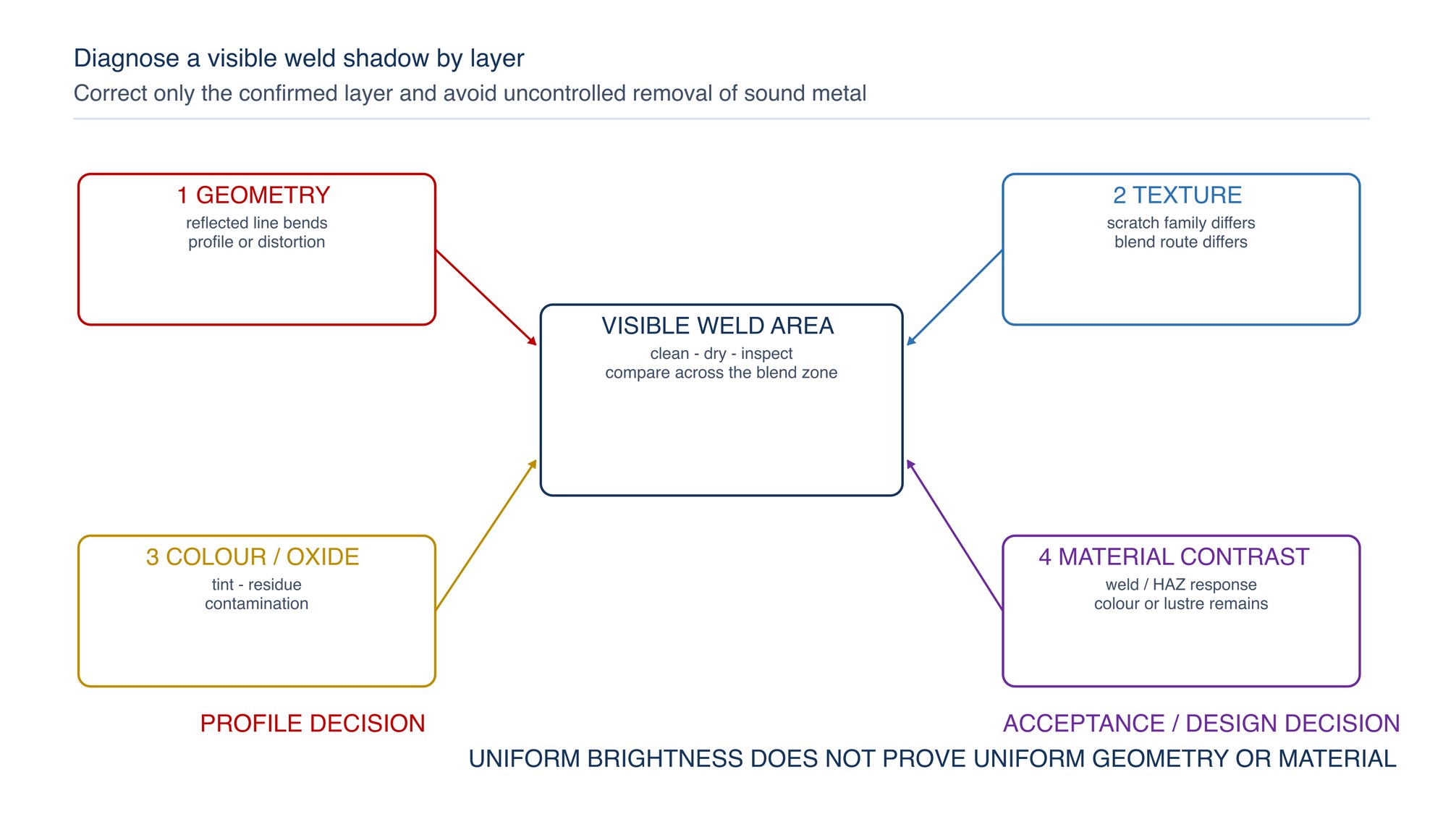
Diagnose visible weld shadow by layer
A visible weld shadow can be a reflected wave from distortion or a low blend, a texture halo from a different abrasive history, residual heat tint or oxide, contamination, or a colour and lustre contrast associated with the weld metal and heat-affected zone. These conditions require different responses.
Use a reflected grid first to check geometry. If the line bends across the weld, correct profile only within the dimensional and fabrication limits; polishing cannot remove distortion without changing shape. TWI explains that local weld heating and cooling create expansion, contraction and distortion, with stainless steel particularly sensitive to these effects. [S082; S083]
If geometry is continuous, compare scratch texture and cleanliness. Restore a uniform pattern across a broad blend zone if the weld area received a different abrasive route. Address heat tint and post-weld contamination using the applicable restoration process. If colour or lustre contrast remains after geometry, texture and cleanliness are controlled, recognise that the weld may remain visible. BSSA notes that a flushed and polished weld can retain slight colour or texture contrast, while ASSDA notes that weld microstructure may limit uniform mirror appearance. [S170; S163]
Select the corrective stage and blend width
The correction stage must have enough cut to remove the defect while preserving geometry. Starting too fine wastes time and adds heat; starting too coarse creates unnecessary rework. Test on a representative area or sample when the route changes.
| Defect depth or condition | Effective starting level | Blend-zone principle | Release signal |
|---|---|---|---|
| Surface film or loose residue | Compatible cleaning | Clean beyond the visible boundary | Dry surface remains mark-free |
| Fine swirls or compound haze | Final polish or colouring stage with controlled cut | Cover the complete affected area | Swirls absent under changing light pattern |
| Fine preparation lines | Cutting compound or pre-polish stage | Rework a broad uniform zone | One fine field with no coarse lines |
| Deep scratch or weld-grinding furrow | Earlier abrasive refinement | Widen until no trench or halo remains | Defect removed and profile continuous |
| Geometry loss, distortion or inherent weld contrast | Engineering or fabrication decision authority | Do not expand removal without part acceptance | Accepted disposition or revised part |
For exact abrasive grade, compound, wheel construction, machine compatibility, marked operating limit and intended use, Refer to the product label, Technical Data Sheet, or MKTECH representative.
Inspect with complementary views
No single light or measurement releases every polishing defect. Use a clean reference surface or first-off part and keep viewing conditions stable for critical appearance work. [S161; S163]
| Inspection mode | Best at revealing | Common false conclusion | Control point |
|---|---|---|---|
| Reflected straight line or grid | Waves, hollows, weld shadow and edge roll-over | Brightness proves flatness | Move the reflection across the complete area |
| Low-angle directional light | Scratches, swirls, haze, residue and wipe marks | One favourable angle is sufficient | Sweep along and across the process direction |
| Diffuse broad light | Uneven gloss, cloudiness and colour variation | Local shine represents the whole part | Compare complete zones under the same light |
| Magnified clean view | Embedded grit, pits, compound pockets and line depth | Every dark point is contamination | Clean first and compare at more than one angle |
| Profile or dimensional check | Edge loss, low weld blend and distortion | A smooth surface is within tolerance | Use the specified reference and acceptance rule |
| Time-delayed clean recheck | Returning haze, residue bleed and protection marks | Fresh compound film is final appearance | Reinspect dry before protection and delivery |
Prevent recurrence through stage control
Prevention is faster than late correction. Begin each stage with a defined entering surface and a clean dedicated system. Record the abrasive or wheel family, compound function, stage order, work support, travel pattern and inspection method used for the accepted result. The record should identify the controlled combination without turning a process example into a universal setting.
Clean the work, tool contact area, fixture and surrounding zone between stages. Distinguish stage direction or inspection orientation so earlier lines remain visible until removed. Retire loaded, glazed, damaged or contaminated media rather than compensating with pressure. Separate coarse and fine work areas where practical.
Release each stage for geometry, scratch removal, cleanliness and temperature before moving finer. Final brightness is not a substitute for these hold points.
Troubleshoot corrections that do not hold
| Symptom after correction | Likely reason | Next action |
|---|---|---|
| Scratch returns after final buff | Compound filled but did not remove the groove | Clean and return to the stage with adequate cut |
| Haze reappears after standing | Residue or film masked fine scratches | Re-clean, inspect dry and correct the scratch field |
| Swirls change but remain | Final pair or path is still introducing marks | Replace contaminated items and stabilise coverage |
| Compound smear persists in seams | Excess application, heat or inaccessible cleaning | Reduce delivery and use a compatible recess-cleaning method |
| Hot patch becomes brighter and larger | Extra dwell is increasing heat and local removal | Stop, cool and correct loading, support and movement |
| Orange peel worsens | Fine polishing continues after the stop condition | Re-establish the surface at the last effective earlier stage |
| Gloss remains patchy | Entering surface or contact system is inconsistent | Standardise the scratch field, wheel condition and path |
| New isolated scratches appear | Coarse particle or dirty handling item remains in the route | Quarantine, clean and replace the source before rework |
| Edge becomes progressively softer | Compliant media continues to wrap the transition | Use firmer support and shorter controlled contact |
| Weld halo remains after uniform texture | Geometry, oxide or inherent weld contrast was misclassified | Diagnose each weld layer and avoid uncontrolled removal |
Concise safety reminders
- Inspect abrasives, wheels, compounds, machine, guards, mounting, work support and extraction before use.
- Confirm compatibility and never exceed the lowest marked operating limit in the assembled system.
- Secure the work and keep hair, clothing, jewellery, loose material and hands away from rotating contact and nip points.
- Stop immediately if vibration, irregular running, product damage, rapid heating, smoke or unexpected discolouration develops.
- Control grinding dust, polishing debris, wheel fibres, compound particles and cleaning vapour at source. [S152; S153; S160]
- Review compound and cleaner Safety Data Sheets and apply current Malaysian chemical-risk controls.
- Keep ignition sources away from combustible lint, metal dust and compound deposits; clean using a method suitable for the collected material.
- Use suitable eye, face, hearing, respiratory, hand, body and foot protection. Gloves must not introduce an entanglement hazard at rotating machinery.
- Isolate energy before changing, mounting, dressing, cleaning, clearing or maintaining equipment.
- Follow current site procedures, machine instructions and abrasive-product safety information. [S155]
Practical defect-correction sequence
- Stop the process and secure the part when a defect is found.
- Clean and dry the surface with a compatible non-scratching method.
- Inspect under diffuse, low-angle and reflected-line views.
- Mark the defect boundary without marking the accepted face.
- Classify its signature: directional, rotary, random, film, thermal, geometric or weld-centred.
- Review the stage history and identify when the feature first appeared.
- Inspect the abrasive, wheel, compound, fixture, cleaning media and handling route used at that stage.
- Decide whether the condition is removable surface damage, geometry loss, contamination or material or weld contrast.
- Select the least aggressive stage with enough cut to remove the defect efficiently.
- Establish a broad controlled blend zone and protect adjacent edges and transitions.
- Correct the process cause before touching the part again.
- Rework progressively, cleaning and inspecting between stages.
- Verify geometry, scratch removal, gloss, cleanliness and any specified measurement independently.
- Protect the accepted surface and confirm the defect does not return after final cleaning.
Paint-Booth Airflow and Filtration Fundamentals
Chapter 032 begins on the following page of the printed handbook (page 257), outside this chapter extract.