
Operators, supervisors, tool issuers, maintenance personnel, safety and health teams, technical buyers and application personnel involved in industrial grinding, cutting, sanding, polishing and surface finishing
Task definition; abrasive identification and condition; tool–accessory compatibility; mounting; guards and controls; workpiece restraint; work-area conditions; dust, spark and atmosphere controls; PPE; safe start; stop-work decisions; quarantine and release.
A released trigger is not isolation. Never rely on nominal diameter alone. Do not reduce a wheel bore, enlarge a hole, force a thread, stack accessories or fit an improvised adaptor. Never tie, wedge or bypass a control. Do not remove a guard for visibility or access; change the task method, tool or work arrangement instead. Stop immediately if the start is not smooth and stable. Isolate before inspection. Never test an uncertain abrasive by standing in line with it or bringing it into contact with the work.
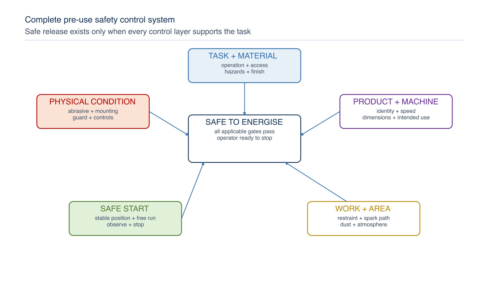
Do not energise the tool until the task, abrasive, machine, mounting system, guard, workpiece and work area form one compatible control system. A failed check leads to correction, quarantine or escalation—not a trial run.
A pre-use check is a decision process, not a quick glance. It prevents a correct product being used on the wrong tool, a sound tool being used with a damaged abrasive, or an apparently simple task being started in an unsafe area. The decision must follow the actual product marking, machine information, material and work arrangement. [S275; S285; S286; S326]
Chapter objectives
After this chapter, the reader should be able to:
- apply four consistent outcomes: proceed, correct, quarantine or escalate;
- define the task and intended abrasive operation before product selection;
- verify product identity, marking, dimensions, attachment and permitted speed;
- recognise product conditions requiring quarantine;
- check the tool, mounting system, guard, handle and controls while isolated;
- confirm workpiece restraint, cut closure, offcut movement and operator position;
- assess sparks, dust, atmosphere, access, lighting and simultaneous work;
- select the correct product-family branch;
- conduct a controlled free-running start where applicable;
- stop safely when conditions change; and
- use a concise release checklist before work begins.
Use four decision outcomes
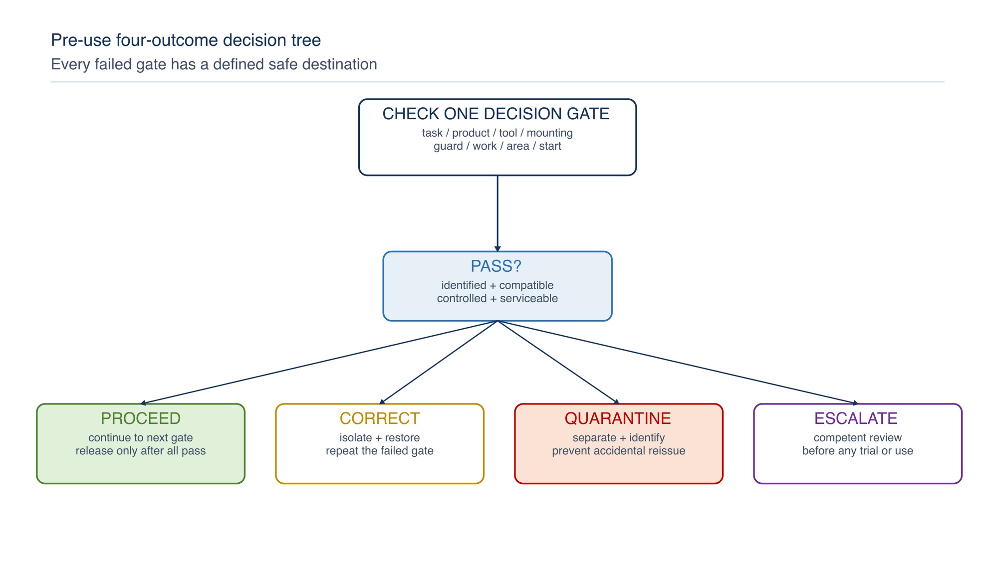
Every check should end in one of four unambiguous outcomes.
| Outcome | Meaning | Typical action |
|---|---|---|
| Proceed | The condition is identified, compatible and controlled | Continue to the next gate; energise only after all gates pass |
| Correct | The issue can be restored safely before use | Isolate, correct, reinspect and repeat the affected gate |
| Quarantine | The abrasive, tool or component may be damaged, defective or unidentifiable | Remove from service, identify it and prevent accidental reissue |
| Escalate | Compatibility, hazard or required control cannot be confirmed at operator level | Refer to a competent supervisor, maintenance person, safety specialist or technical representative |
“Proceed” applies only to the condition checked. The task is released only when every applicable gate passes. If the task, material, tool, abrasive, area or control changes, return to the first affected gate.
Gate 1 — Define the task and material
State the operation in practical terms before choosing an abrasive:
- material and coating to be contacted;
- cutting, stock removal, weld blending, deburring, cleaning, finishing or polishing;
- geometry, access and required finish;
- portable or stationary machine;
- dry or wet process, where the equipment and product permit it;
- expected spark, heat, dust and debris path;
- workpiece support, restraint and movement; and
- adjacent people, equipment and processes.
Do not substitute one operation for another because the product fits the spindle. A cutting-off wheel is intended for peripheral cutting and must not be used for side grinding. A grinding wheel is not automatically suitable for cutting. Select from the marked intended use and restrictions. [S278; S279; S326; S327]
Decision: If the material, operation or access condition is uncertain, escalate before selecting the abrasive. If the job can be completed by a lower-risk method that achieves the required result, use that method.
Gate 2 — Read the abrasive identity
Confirm that the product can be positively identified. Depending on product family, useful information may include:
- manufacturer or supplier identity;
- product name, type or code;
- dimensions;
- abrasive specification, grit or grade;
- intended operation or application symbol;
- maximum permitted rotational speed;
- direction of rotation;
- expiry or use-by information where applicable;
- restriction and PPE symbols; and
- traceability or batch information.
Do not guess from colour, shape, packaging resemblance or a handwritten description. Keep labels and packaging with the product until issue is complete. If essential identity or marking is illegible, quarantine the product.
When an exact product value is required, Refer to the product label, Technical Data Sheet, or MKTECH representative.
Gate 3 — Prove tool–accessory compatibility
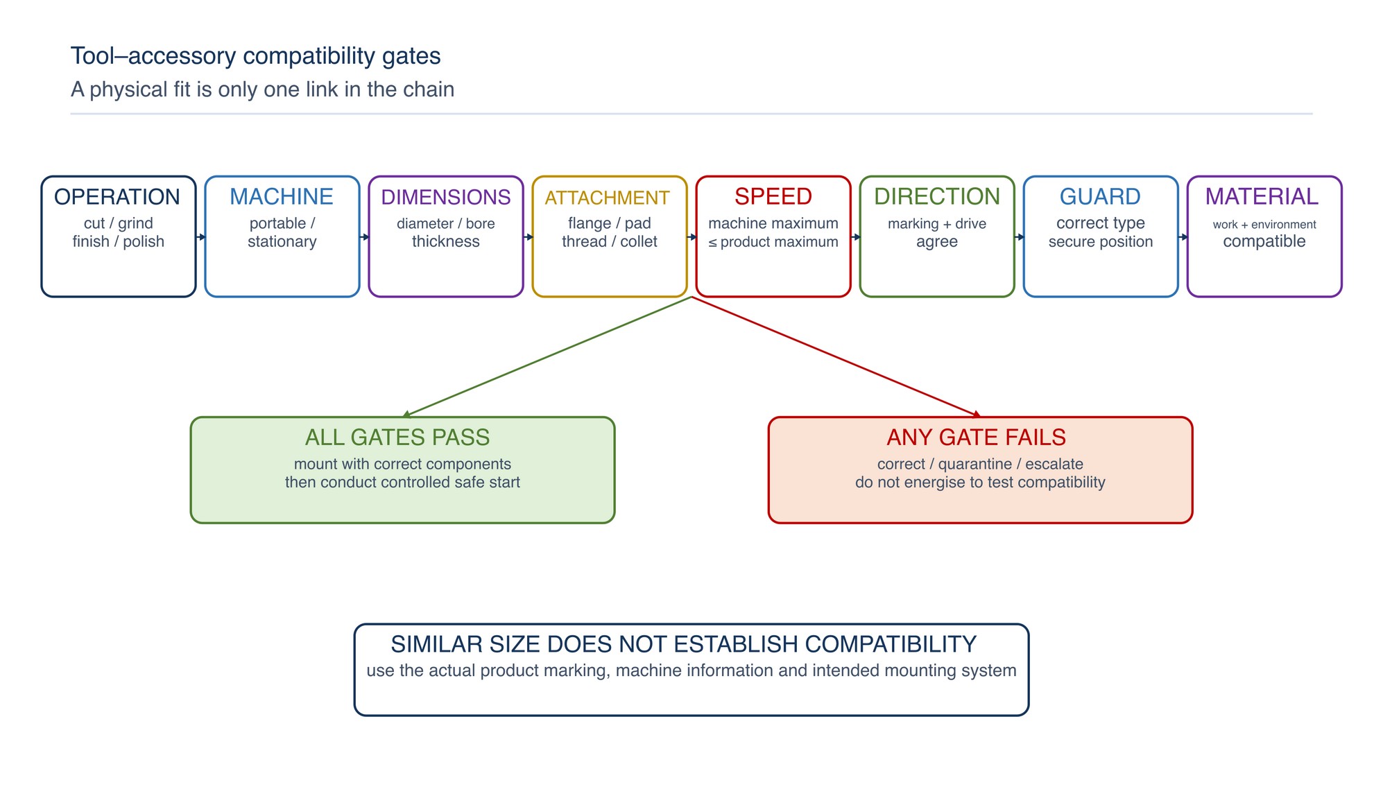
Compatibility is a chain. All links must match:
- Intended operation: cutting, grinding, sanding, blending, cleaning or polishing.
- Machine type: the accessory is intended for the actual portable or stationary machine.
- Dimensions: diameter, width or thickness, bore, arbor and working clearance fit the machine and guard.
- Attachment: thread, flange, backing pad, chuck, collet, mandrel or hub is the intended system.
- Speed: the machine’s maximum no-load speed does not exceed the abrasive’s marked maximum permitted speed.
- Direction: directional products and machines run in the indicated direction.
- Guarding: the correct guard can be fitted and positioned without modification.
- Material and environment: the product is suitable for the work material and dry, wet, dusty or potentially hazardous conditions.
Never rely on nominal diameter alone. Two products of similar size may have different attachment systems, speed limits, intended uses or guard requirements. Do not reduce a wheel bore, enlarge a hole, force a thread, stack accessories or fit an improvised adaptor.
Gate 4 — Inspect the abrasive condition
Inspect in good light before fitting. Handle the product by its strong, intended support surfaces and avoid bending, dropping or striking it.
| Product condition | Decision |
|---|---|
| Cracked, chipped, torn, delaminated, distorted, crushed or impact-damaged | Quarantine |
| Bore, thread, hub, backing, joint or attachment damaged | Quarantine |
| Wet, chemically contaminated, oil-soaked or affected by unsuitable storage | Quarantine pending competent assessment |
| Marking needed for selection or speed verification is unreadable | Quarantine |
| Applicable expiry or use-by date has passed | Quarantine |
| Uncertain drop, impact, exposure or storage history | Quarantine pending assessment |
| Normal, identifiable and free from visible damage | Continue to the product-family check |
For products and applications requiring an inspection test such as a ring test, use the correct method only on product types for which that test is applicable and only by a trained person. A test result does not override visible damage, unsuitable storage or incorrect mounting. [S285; S286]
Gate 5 — Isolate and inspect the machine
Disconnect the electrical supply, remove the battery, isolate pneumatic or hydraulic energy, or apply the machine’s isolation method before fitting, adjustment, clearing or inspection. A released trigger is not isolation.
Check:
- model, rated capacity and maximum no-load speed information;
- spindle, arbor, chuck, collet, mandrel or drive condition;
- threads, keys, shoulders and contact surfaces;
- bearings, play, unusual resistance and run-out;
- power lead, plug, battery, charger, air hose and couplings;
- start, stop, dead-man or hold-to-run control as fitted;
- auxiliary handle and required machine supports;
- vents, extraction ports and cooling paths; and
- evidence of unauthorised modification or previous impact.
Quarantine a tool with a damaged guard, defective control, exposed conductor, cracked housing, loose spindle, abnormal run-out or uncertain safe condition. Maintenance release is required before reissue. [S280; S281; S282; S283; S284; S328]
Gate 6 — Confirm mounting components
Use the flange, nut, backing pad, adaptor, washer, blotter, chuck, collet, mandrel or hub specified for the abrasive and machine combination. Mounting surfaces should be clean, flat, undamaged and correctly seated.
Reject these practices:
- mixing unmatched flanges or nuts;
- omitting a required component;
- using a component that is bent, burred, worn or cracked;
- forcing the abrasive onto the spindle or into a collet;
- using packing, tape or makeshift washers to remove looseness;
- stacking discs to increase thickness;
- using excessive tightening force; or
- modifying the guard to accommodate an unsuitable accessory.
Tightening should secure the product without distorting it. Use only the intended tool and method. After mounting, rotate by hand where the machine design permits and confirm free clearance from the guard, work rest and machine structure.
Gate 7 — Verify guards, handles and controls
The guard is part of the machine–abrasive system. Confirm that it is the correct type for the operation, securely installed, undamaged and positioned to maximise protection while allowing controlled access to the work.
Check that:
- the guard covers the required portion of the abrasive;
- the opening is directed away from the operator and others as far as practicable;
- the guard cannot contact the accessory during run-up or use;
- the auxiliary handle is fitted where required and enables stable two-hand control;
- the switch operates freely and returns or latches only as designed;
- emergency stopping means are accessible on stationary equipment; and
- protective screens do not replace required eye and face protection.
Never tie, wedge or bypass a control. Do not remove a guard for visibility or access; change the task method, tool or work arrangement instead.
Gate 8 — Secure and support the workpiece
Restraint must control both the workpiece and any material that will be released.
Before starting, determine:
- how the part is clamped, located or supported;
- whether the contact force can rotate, lift or eject it;
- how a cut will close or open as residual stress is released;
- where the offcut will fall, swing or roll;
- whether the abrasive can be pinched or trapped;
- whether the operator’s hands or body enter the line of cut;
- whether hoses or cables can be caught; and
- whether hot or sharp material can strike people or ignite nearby fuel.
Support the work so the kerf remains controlled and the wheel is not twisted. Small parts should not be hand-held against a powered abrasive. On a stationary grinder, set and maintain the work support in accordance with the machine instructions and the actual wheel arrangement.
Gate 9 — Prepare the work area
Walk the entire operating and receiving area, including the opposite side, lower level and extraction path.
| Area factor | Release question |
|---|---|
| People and access | Are bystanders excluded and is the escape route clear? |
| Lighting and footing | Can the operator see the contact point and maintain stable balance? |
| Sparks and hot particles | Are combustibles removed or protected along the complete travel path? |
| Flammable atmosphere | Are vapours, gases, residues, containers, drains and connected systems controlled? |
| Dust | Is dust captured without creating an incompatible fire or explosion path? |
| Water and moisture | Are electrical, abrasive, material and waste systems suitable for the method? |
| Noise and vibration | Are engineering controls and exposure arrangements in place? |
| Simultaneous work | Can nearby welding, spraying, cleaning, lifting or vehicle movement affect the task? |
| Housekeeping | Are trip hazards, loose debris and accumulated dust removed safely? |
If sparks, dust, fragments or noise cross the prepared boundary, correct the area or relocate the task. Abrasive work on used containers, pipework or equipment that may retain hazardous residue requires a controlled site method before release.
Gate 10 — Confirm engineering controls and PPE
Engineering controls come first. Confirm required enclosure, local extraction, spark containment, screens, work supports, ventilation and noise controls are operating and compatible with the material.
Select PPE from the task assessment and product symbols. The ensemble may include:
- safety eyewear and face protection;
- suitable hearing protection;
- task-selected respiratory protection;
- protective clothing and footwear;
- gloves appropriate to material handling and entanglement risk; and
- head or body protection for the work environment.
Check fit and compatibility. Safety glasses must not prevent a face shield sitting correctly; eyewear must not break a respirator seal; hearing protection must remain correctly seated; loose clothing, jewellery and hair must not approach rotating equipment. PPE does not correct an incompatible abrasive, missing guard or uncontrolled atmosphere.
Select the product-family branch
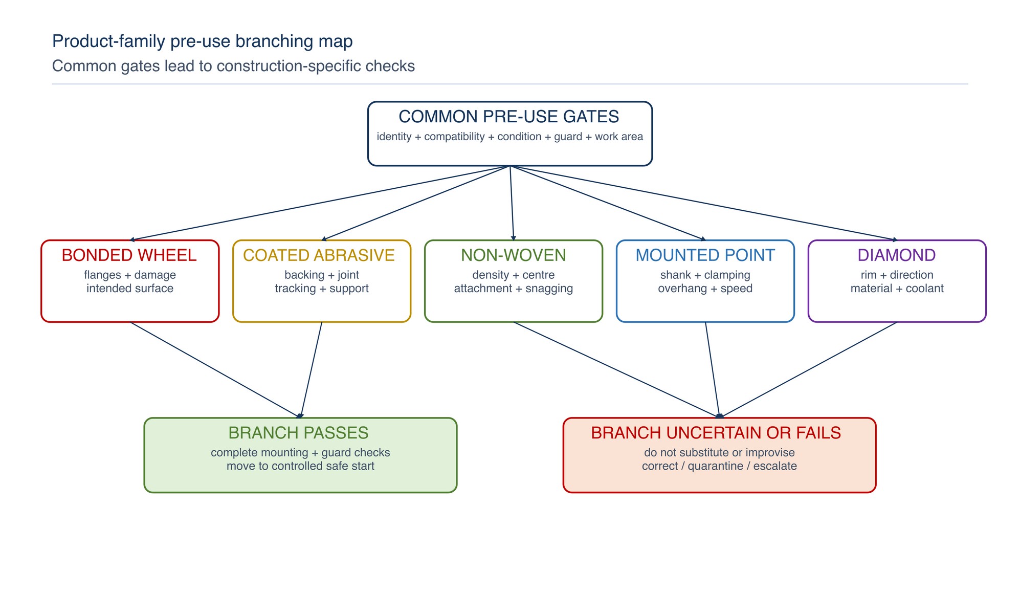
| Product family | Additional pre-use focus |
|---|---|
| Bonded grinding wheel | Marking, dimensions, speed, flange contact, blotter where applicable, damage inspection, correct guard and intended grinding surface |
| Bonded cutting-off wheel | Cutting designation, correct cut-off guard, straight peripheral cut, work support and freedom from side load |
| Fibre or flap disc | Correct backing/support where required, disc condition, thread or flange seating, guard, direction and intended contact angle |
| Coated abrasive belt | Belt dimensions, joint and edge condition, tracking direction, tension, platen/contact wheel condition and enclosure |
| Non-woven product | Correct density or grade for the task, centre or backing integrity, attachment, speed and avoidance of snagging edges |
| Mounted point or small wheel | Correct shank/mandrel, insertion and clamping, overhang control, speed relationship and guard or enclosure arrangement |
| Diamond or superabrasive product | Intended material and method, direction, segment or rim condition, mounting, coolant requirements where applicable and machine suitability |
| Polishing mop or brush-type accessory | Hub and retention, speed, direction, loose sections, compound compatibility, enclosure and entanglement control |
The branch check supplements the common gates; it does not replace them.
Portable angle-grinder branch
For a portable angle grinder, verify:
- the abrasive is intended for an angle grinder and the planned operation;
- the marked maximum permitted abrasive speed is not below the machine’s maximum no-load speed;
- diameter, bore or thread and thickness suit the machine and guard;
- the correct guard and auxiliary handle are fitted;
- flanges, nut or backing pad are the intended, undamaged set;
- the workpiece is clamped and the spark or fragment path is controlled;
- the lead, battery or air hose remains clear of the abrasive and hot work; and
- the operator can maintain stable two-hand control without overreaching.
For cutting, enter the work in line with the cut and avoid twisting or side pressure. For grinding, use only a wheel surface intended for grinding and maintain the product’s recommended working angle. [S326; S327]
Stationary grinding branch
For a bench, pedestal or other stationary grinding machine, confirm:
- machine isolation during mounting and adjustment;
- wheel type, size and speed compatibility;
- wheel condition and applicable inspection method;
- correct flanges, blotters and mounting sequence where required;
- enclosure, guard and tongue or opening controls as designed;
- stable and correctly positioned work rest;
- screen condition and visibility;
- extraction and debris collection;
- emergency stop access; and
- a clear operator position outside the likely fragment path during start-up.
Do not adjust a work rest or guard while the wheel is moving. Numeric clearances and machine-specific settings must follow the applicable machine instructions and workplace procedure. [S284; S286; S287]
Conduct a controlled free-running start
After all pre-use gates pass:
- clear tools, keys, loose parts and packaging;
- confirm the abrasive rotates freely and the guard is secure;
- warn or exclude nearby personnel;
- establish a stable stance and two-hand control where applicable;
- position the body outside the likely fragment path;
- start without contact with the workpiece;
- allow the product to reach stable operating speed for the period required by its instructions; and
- listen and observe for abnormal vibration, noise, run-out, rubbing, movement, smell or control behaviour.
Stop immediately if the start is not smooth and stable. Isolate before inspection. Never test an uncertain abrasive by standing in line with it or bringing it into contact with the work.
Apply stop-work logic during operation
Pre-use release is not permanent. Stop in a controlled manner when:
- vibration, noise, run-out or heat changes unexpectedly;
- the abrasive chips, tears, loads, glazes, sheds or loses cutting efficiency abnormally;
- the guard, handle, work support or workpiece moves;
- the wheel binds, the cut closes or the tool kicks;
- sparks, dust or fragments leave the controlled area;
- extraction, ventilation, lighting or power quality is lost;
- a bystander enters the exclusion zone;
- flammable material, vapour or an unexpected coating is discovered;
- the task no longer matches the selected operation; or
- the operator loses stable posture or clear sight of the contact point.
Allow the abrasive to stop completely before setting down a portable tool or approaching a stationary wheel. Isolate, identify the cause and repeat the relevant decision gates before restart.
Quarantine and return-to-service control
A quarantined item should be physically separated from usable stock, clearly identified and protected from accidental reissue. Record enough information to support a competent disposition: item identity, observed condition, date, task, machine and person reporting.
Do not return an abrasive or tool to service because the defect is difficult to see on a second inspection. Abrasives are not repaired by adhesive, trimming, re-boring or re-labelling. Tools return only after the responsible maintenance or inspection process confirms safe condition.
After normal use, let the accessory stop fully, isolate the machine and inspect before storage or reissue. Store abrasives in their intended packaging and environmental conditions, protected from impact, moisture, contamination, distortion and uncontrolled temperature.
Troubleshoot a failed pre-use gate
| Symptom or failed check | Likely control issue | Corrective direction |
|---|---|---|
| Product fits but speed cannot be confirmed | Incomplete marking or machine information | Do not energise; identify both ratings or escalate |
| Wheel does not seat flat | Dirty, damaged or incompatible flange/attachment | Isolate; clean and inspect; replace the incorrect or damaged component |
| Guard will not close around accessory | Wrong product size, thickness or guard type | Select the correct combination; never modify or remove the guard |
| Abrasive rubs during hand rotation | Incorrect seating, distortion, guard contact or spindle fault | Isolate, remove and inspect the complete mounting system |
| Excessive vibration at free run | Damage, imbalance, mounting error, run-out or machine defect | Stop, isolate and quarantine the suspected item |
| Cut begins to pinch | Inadequate support, residual stress or incorrect cutting path | Stop safely; redesign support and cut sequence before restarting |
| Dust escapes capture | Poor hood position, airflow, filter condition or unsuitable system | Stop; restore effective compatible control and reassess the area |
| Sparks reach outside the boundary | Tool direction, screen, airflow or task position has changed | Stop; extend or redesign containment and recheck receiving areas |
| Operator cannot hold stable posture | Access, tool size, handle position or work height is unsuitable | Reposition or select a more suitable method and support |
| Uncertain product application | Selection information is insufficient | Refer to the product label, Technical Data Sheet, or MKTECH representative. |
Supervisor release questions
For higher-risk or non-routine work, the supervisor should be able to answer:
- Is the task defined and is this the preferred safe method?
- Are the material, coating and potential residues understood?
- Can the abrasive and machine be positively identified?
- Has the complete compatibility chain been checked?
- Are product and machine free from damage or modification?
- Are mounting, guard, handle and control arrangements correct?
- Is the workpiece restrained through the complete operation?
- Are sparks, dust, noise, heat and released material controlled?
- Are atmosphere, adjacent processes and people controlled?
- Are engineering controls and PPE available and effective?
- Does the operator understand start, stop and escalation actions?
- Will any change return the job to reassessment?
The release should be proportionate to the task. A documented permit may be required for hot work, confined spaces, hazardous atmospheres, isolation or other site-controlled activities.
Pre-use safety release checklist
- [ ] Task, material, operation and required finish are defined.
- [ ] Abrasive identity and essential marking are legible.
- [ ] Intended use, dimensions, attachment, direction and speed are compatible.
- [ ] Abrasive is within applicable date and free from damage, contamination and distortion.
- [ ] Tool is isolated and its spindle, drive, supply and controls are serviceable.
- [ ] Correct mounting components are clean, undamaged and properly seated.
- [ ] Correct guard, handle, work support and protective devices are installed.
- [ ] Workpiece and offcut are restrained; binding and released stress are controlled.
- [ ] Operator stance, access, visibility and cable or hose routing are stable.
- [ ] Bystanders and simultaneous operations are controlled.
- [ ] Spark, fragment, heat and dust paths remain inside the prepared boundary.
- [ ] Atmosphere, combustibles, residues and connected equipment are controlled.
- [ ] Compatible extraction, ventilation and engineering controls are operating.
- [ ] Task-selected PPE is fitted and compatible.
- [ ] Free-running start position and stop-work actions are understood.
Preventive Maintenance for Grinding Machines
This next-chapter heading appears on the final page of this chapter’s extract (page 460); the Preventive Maintenance for Grinding Machines content is covered in the following chapter of the printed handbook, outside this chapter extract.