
Production managers, workshop supervisors, operators, maintenance technicians, safety and health personnel, tool-room teams and technical buyers responsible for pneumatic grinders, die grinders, sanders and polishers
Air supply; isolation and pressure release; hoses and couplings; filters, regulators and lubricators; air quality; throttles and governors; exhaust; spindle, collet and guards; lubrication; free-speed verification; condition monitoring; cleaning; competent repair; release and troubleshooting.
Do not rely on the throttle alone. A stuck valve, accidental contact, wrongly connected supply or trapped pressure can cause unexpected rotation. Remove from service any tool that starts unexpectedly, continues to run, responds intermittently or leaks severely through the control. Never use the air hose to carry or suspend the tool.
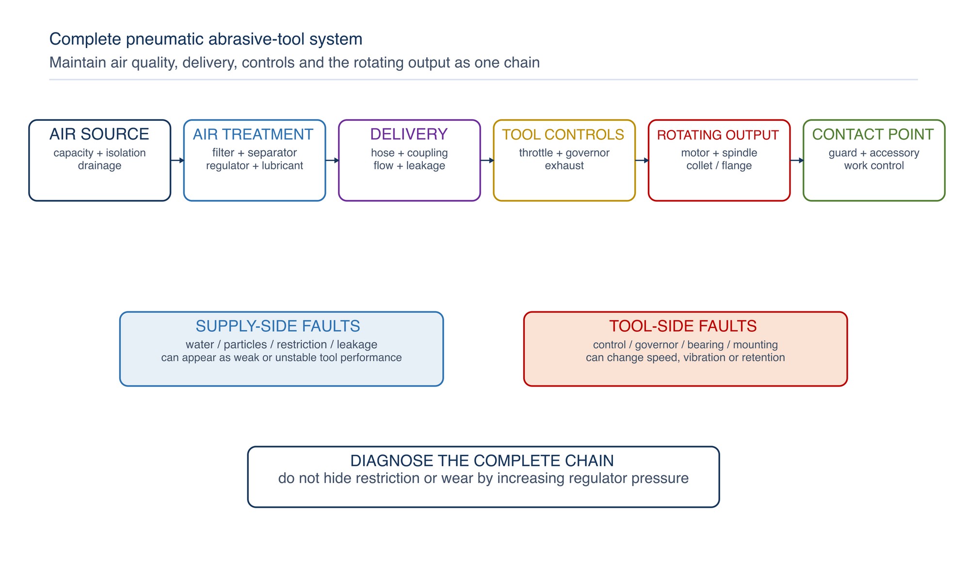
A pneumatic abrasive tool is only as reliable as the complete system supplying and controlling it. Maintain the tool, hose, coupling, air treatment, pressure control, mounting system and accessory as one compatible operating chain.
Pneumatic tools are compact and robust, but their speed and condition can be affected by air pressure, flow restriction, water, particles, lubrication, hose damage, leakage and internal wear. Abrasive dust can also enter controls and exhaust passages. Preventive maintenance must therefore follow the complete route from the compressed-air connection to the abrasive contact point. [S280; S281; S282; S333; S336]
Chapter objectives
After this chapter, the reader should be able to:
- map the complete pneumatic tool system;
- isolate, bleed and disconnect the tool safely;
- inspect hoses, couplings, retainers and routing;
- maintain filters, drains, regulators and lubricators;
- understand particles, water and oil contamination;
- distinguish lubricated and non-line-lubricated tool arrangements;
- inspect throttles, lock-offs, governors, exhausts and guards;
- check spindles, collets, mandrels and accessory mounting;
- recognise when calibrated free-speed verification is required;
- diagnose weak power, speed drift, leakage, noise and vibration systematically;
- control cleaning and internal repair; and
- complete a controlled return-to-service check.
Treat the air tool as a system
| System element | Main function | Typical maintenance concern |
|---|---|---|
| Supply header or drop | Provides air volume and pressure | Contamination, drainage, isolation, capacity |
| Filter and separator | Removes particles and liquid | Loading, drainage, damage, bypass |
| Regulator | Controls delivered pressure | Drift, tampering, poor location, gauge condition |
| Lubricator where required | Introduces specified lubricant | Empty bowl, wrong oil, over-feed, poor placement |
| Hose and coupling | Carries air to the tool | Leakage, damage, restriction, whip, trip hazard |
| Tool inlet and motor | Converts air energy to rotation | Dirt, water, wear, lubrication, speed change |
| Governor or speed control | Limits or regulates speed where fitted | Wear, contamination, unauthorised adjustment |
| Spindle and mounting | Retains and drives the abrasive | Run-out, wear, damaged thread or collet |
| Guard and controls | Protect and stop the operator | Damage, bypass, slow return, incorrect position |
Inspecting only the tool body can miss the real cause of poor performance. A blocked filter, undersized coupling, wet hose, excessive length or leaking joint can reduce power while an incorrect regulator setting or internal governor fault can create an unsafe condition.
Establish tool identity and service basis
Before maintenance, confirm:
- manufacturer, model and serial number;
- intended tool family and operation;
- rated speed and accessory capacity information;
- inlet connection and approved supply arrangement;
- lubrication method;
- guard, handle, spindle, collet or chuck configuration;
- product, safety, parts and maintenance instructions;
- service history, previous repairs and modifications; and
- authorised replacement parts and responsible service level.
Keep the nameplate and warnings legible. Do not identify a tool by colour, general shape or a similar model. A replacement motor, governor, arbor housing or nameplate can change the controlled configuration and requires the correct parts basis.
When an exact tool, pressure, lubricant, part, speed or service value is required, Refer to the product label, Technical Data Sheet, or MKTECH representative.
Separate maintenance roles
- Operator care: external condition check, approved cleaning, hose inspection, accessory change and defect reporting.
- Tool-room inspection: controlled issue and return, identity check, guard and control inspection, leakage observation and scheduled status.
- Competent maintenance: isolation, dismantling within authority, cleaning, lubrication, parts replacement and specified tests.
- Specialist or authorised service: governor, rotor, safety control, spindle assembly or other work reserved by the manufacturer.
Do not allow production familiarity to substitute for repair competence. Internal air-tool parts can be spring-loaded, precisely fitted or safety-critical. Incorrect assembly may change free speed, braking, throttle return, vibration or accessory retention. [S329; S333]
Isolate, bleed and disconnect
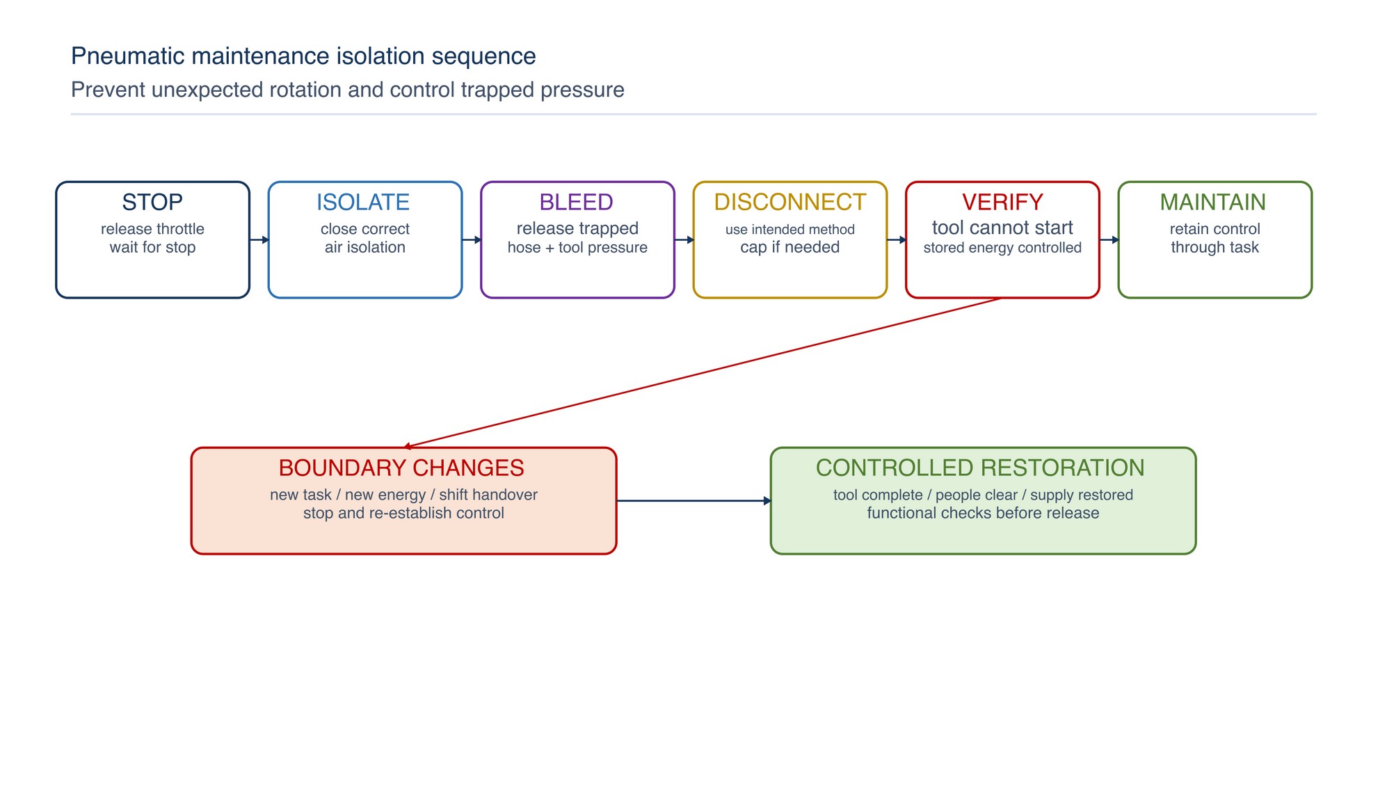
Before accessory change, adjustment, clearing or maintenance:
- release the throttle and allow the accessory to stop;
- close the correct air isolation point;
- bleed trapped pressure from the hose and tool;
- disconnect the air supply using the intended method;
- secure or cap the hose where contamination or movement is possible;
- verify that the tool cannot start; and
- control any stored mechanical energy or hot components.
Do not rely on the throttle alone. A stuck valve, accidental contact, wrongly connected supply or trapped pressure can cause unexpected rotation. Group or fixed-installation work may require the workplace energy-control procedure rather than simple disconnection. [S275; S331; S333]
Inspect hoses, couplings and retainers
Inspect the complete hose length in good light. Look for:
- cuts, abrasion, blisters, hardening, softening or exposed reinforcement;
- crushed, kinked or heat-damaged areas;
- damaged threads, nipples, sockets or locking parts;
- loose clamps, makeshift repairs or incompatible fittings;
- leakage at joints, swivels and strain points;
- contamination inside disconnected ends;
- missing positive retention where required;
- hose weight or pull affecting tool control; and
- routing across sharp edges, traffic routes, hot work or liquids.
Quarantine visibly damaged or unsafe hose. Do not repair pressure hose with tape, wire, ordinary clamps or unapproved splices. Couplings should connect fully, lock correctly and remain suitable for the hose, pressure and flow duty. [S336]
Control pressure and flow at the tool
Pressure and flow are different. A gauge can show expected static pressure while restriction causes a large drop during operation. Conversely, an incorrect or bypassed regulator may expose the tool to excessive supply conditions.
For performance complaints, check:
- regulator identity, condition and tamper control;
- gauge condition and location;
- pressure under the specified operating test;
- filter loading and separator restriction;
- coupling and hose internal size;
- hose length, kinks and manifold demand;
- simultaneous users on the branch;
- leakage; and
- tool inlet screen or fitting restriction.
Never increase regulator pressure to compensate for a worn motor, blocked filter, undersized hose or overloaded abrasive. Correct the cause using the actual tool and system information.
Maintain filters, separators and drains
Air-treatment equipment should be accessible, correctly oriented and protected from impact.
| Component | Check | Corrective direction |
|---|---|---|
| Filter element | Loading, damage, pressure indication where fitted | Replace by condition or specified interval |
| Bowl | Cracks, clouding, chemical attack, secure fit | Depressurise and replace damaged components |
| Drain | Water removal, blockage, automatic-drain function | Clean or repair without releasing pressure unsafely |
| Separator | Collection, differential condition, leakage | Restore effective separation and sealing |
| Regulator | Stable control, adjustment lock, gauge | Verify by the specified method; prevent tampering |
| Lubricator | Correct lubricant, level, feed and location | Service only where the tool system requires it |
Drainage should not discharge onto walkways, electrical equipment or people. Treat condensate according to its actual oil and contaminant content.
Understand compressed-air contamination
ISO 8573-1 classifies compressed-air purity in relation to particles, water and oil and identifies other possible contaminants. [S335] For abrasive tools, contamination can:
- abrade motor vanes, bearings, valves and governors;
- cause corrosion, sticking or freezing;
- wash out or degrade lubricant;
- block small passages or exhaust silencers;
- contaminate the workpiece or finished surface;
- carry hazardous process material into maintenance work; and
- change tool speed or power.
Do not assign a purity class from appearance or install a finer filter without checking flow capacity and system design. Sample or measure at a location representative of the tool supply when quantitative air quality is required.
Apply the correct lubrication method
Pneumatic tools may use line lubrication, periodic inlet lubrication, sealed lubrication or a model-specific combination. One method cannot be assumed for every tool.
Use only the lubricant, quantity, location and interval specified for the actual tool. Too little lubrication can accelerate wear and sticking. Too much can contaminate the work, exhaust into the breathing zone, load silencers, attract dust or affect process finish.
Check that a line lubricator is close enough and adjusted appropriately for the intended branch. Do not feed lubricated air into tools or processes that require oil-free supply. Keep lubricant containers identified, clean and closed; do not mix oils by appearance.
Maintain throttle, lock-off and shut-off controls
The throttle should move freely, start only by deliberate action and return reliably when released. Check:
- lever, trigger or twist control condition;
- lock-off or safety latch operation;
- spring return and valve movement;
- dirt, sticky residue or damage around the control;
- unintended continuous running;
- air leakage when released; and
- unauthorised ties, wedges or modifications.
Remove from service any tool that starts unexpectedly, continues to run, responds intermittently or leaks severely through the control. Do not flush an assembled control with an unapproved solvent or lubricate it externally to hide a sticking fault.
Protect governors and speed-control assemblies
Where fitted, the governor is a safety-relevant speed-control device. Internal wear, contamination, incorrect springs, mismatched parts or unauthorised adjustment can change tool speed.
Do not:
- dismantle a sealed or unit-replacement governor beyond instructions;
- bend springs or modify weights;
- alter ports or exhaust restrictions to gain power;
- mix parts between tool models;
- infer safe speed from sound; or
- fit an abrasive until required free-speed checks pass.
After relevant repair, confirm the correct assembly and use the specified calibrated test method before release. [S280; S333]
Inspect exhaust and silencing
The exhaust affects noise, back pressure, contamination and operator exposure.
Check that:
- exhaust openings are clear;
- silencers or mufflers are present and serviceable;
- exhaust direction does not blow dust toward the face or workpiece;
- ice, oil mist or debris is not accumulating abnormally;
- deflectors and hoses are secure; and
- replacement components do not create excessive restriction.
A blocked silencer may reduce power or affect speed control. Removing it may increase noise, debris discharge and exposure. Replace or service it using the approved arrangement.
Maintain spindle, collet and accessory mounting
Inspect the rotating output system for:
- spindle, arbor or shaft straightness and play;
- thread, shoulder and flange condition;
- collet slots, taper, nut and seating surfaces;
- chuck or mandrel wear;
- spindle-lock condition where fitted;
- damage from overtightening, impact or abrasive contact;
- correct insertion and clamping of shanks; and
- free rotation and guard clearance.
Do not force a shank, pack a worn collet, dress damaged threads by trial or substitute a flange because it fits. Quantitative run-out, shank insertion and overhang limits follow the actual tool and accessory instructions.
Maintain guards, handles and tool body
Replace a guard that is bent, cracked, severely worn or affected by a wheel failure. Check the clamp, fastener and indexing system so the guard remains secure in the intended position. [S333]
Also inspect:
- side handle and mounting threads;
- housing cracks, loose screws and missing covers;
- label and direction marking;
- inlet fitting and exhaust deflector;
- suspension eye or balancer point where fitted;
- reaction bar or support for relevant tools; and
- evidence of grinding, drilling or unauthorised modification.
Never use the air hose to carry or suspend the tool.
Verify free speed correctly
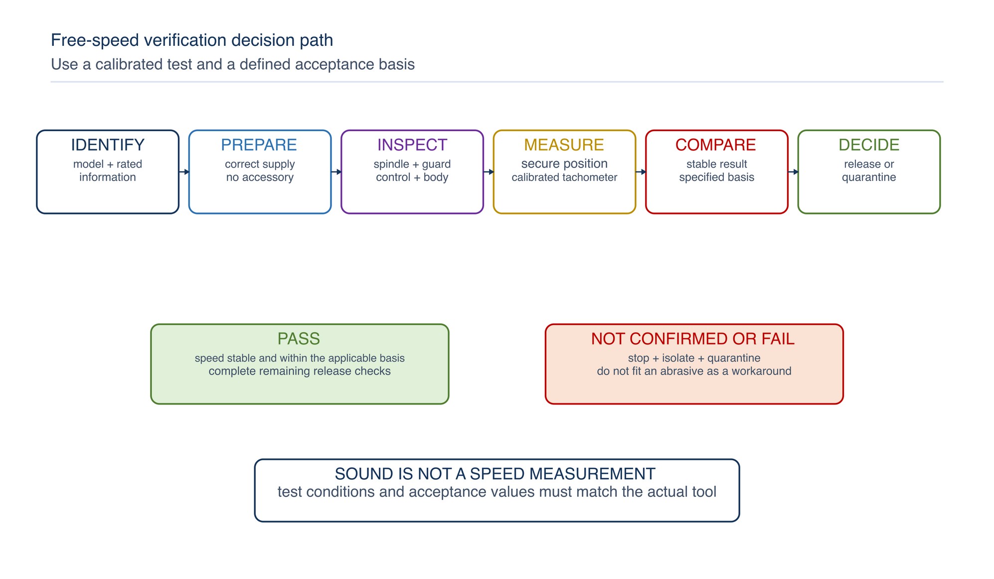
Free-speed verification is required where specified by the tool instructions, after relevant repair and when speed-control condition is uncertain. The test should be performed by a competent person using a calibrated tachometer and the correct no-accessory arrangement. [S333]
Before testing:
- confirm exact tool identity and rated information;
- verify air supply and regulator test conditions;
- remove the abrasive product where the method requires it;
- inspect spindle, guard, control and tool body;
- secure the tool and control exhaust direction;
- keep people clear of the rotating output;
- record the stable result; and
- compare it with the specified acceptance basis.
If speed exceeds, fluctuates beyond, or cannot be confirmed against the specified basis, isolate and quarantine the tool. Do not fit a lower-speed abrasive as a workaround.
Use condition indicators before failure
Observe changes in:
- free speed and loaded speed behaviour;
- start response and stopping time;
- vibration, noise or roughness;
- housing temperature;
- air consumption and leakage;
- exhaust oil, water, debris or ice;
- spindle play and run-out;
- abrasive finish, chatter, loading or cycle time; and
- repeated hose, coupling or control defects.
Compare like with like: same tool configuration, supply condition, test method and measurement location. One signal is not a complete diagnosis. A power loss may come from the supply, delivery path, throttle, motor, exhaust, accessory or technique.
Clean and repair safely
Pneumatic tools can contain abrasive dust, coating residue, metal fines, oil and cleaning chemicals. Isolate and clean the exterior before opening. Use suitable ventilation, capture and PPE for the deposit.
During internal work:
- keep parts ordered and protected from contamination;
- use the correct disassembly and assembly tools;
- inspect rather than automatically replace every part;
- replace seals, bearings, vanes and safety components by the specified basis;
- use compatible cleaning solvent in a ventilated area;
- apply lubricant only to the required surfaces;
- observe orientation, clearances and tightening methods; and
- prevent dirt entering open air passages.
Repair should be performed by authorised trained personnel where the instructions require it. [S333]
Troubleshoot pneumatic-tool symptoms
| Symptom | Possible system causes | Corrective direction |
|---|---|---|
| Weak power | Supply drop, blocked filter, restrictive hose, leakage, motor wear, loaded abrasive | Test supply under defined conditions; inspect complete chain |
| Speed high or unstable | Regulator, governor, wrong parts, contamination or test error | Stop, isolate and perform competent calibrated verification |
| Tool will not start | Isolation closed, coupling fault, throttle sticking, motor seizure or ice | Bleed and isolate before inspection; do not strike the tool |
| Excessive leakage | Hose, coupling, inlet, valve, seal or housing defect | Locate safely, depressurise and replace the correct component |
| Excessive vibration | Accessory, collet, spindle, bearing, motor or mounting fault | Remove accessory; inspect and measure from tool outward |
| Exhaust heavily oily | Over-lubrication, wrong method, internal condition | Correct lubrication basis and inspect exhaust system |
| Water or ice at exhaust | Drainage, dryer, temperature or air-quality problem | Correct the supply condition; do not rely on extra oil |
| Tool runs after release | Throttle contamination, spring, valve or modification | Quarantine immediately for competent repair |
| Abrasive repeatedly loosens | Mounting wear, incorrect component, vibration or technique | Inspect spindle, collet/flange and accessory compatibility |
| Exact value uncertain | Model-specific data are required | Refer to the product label, Technical Data Sheet, or MKTECH representative. |
Complete a controlled return to service
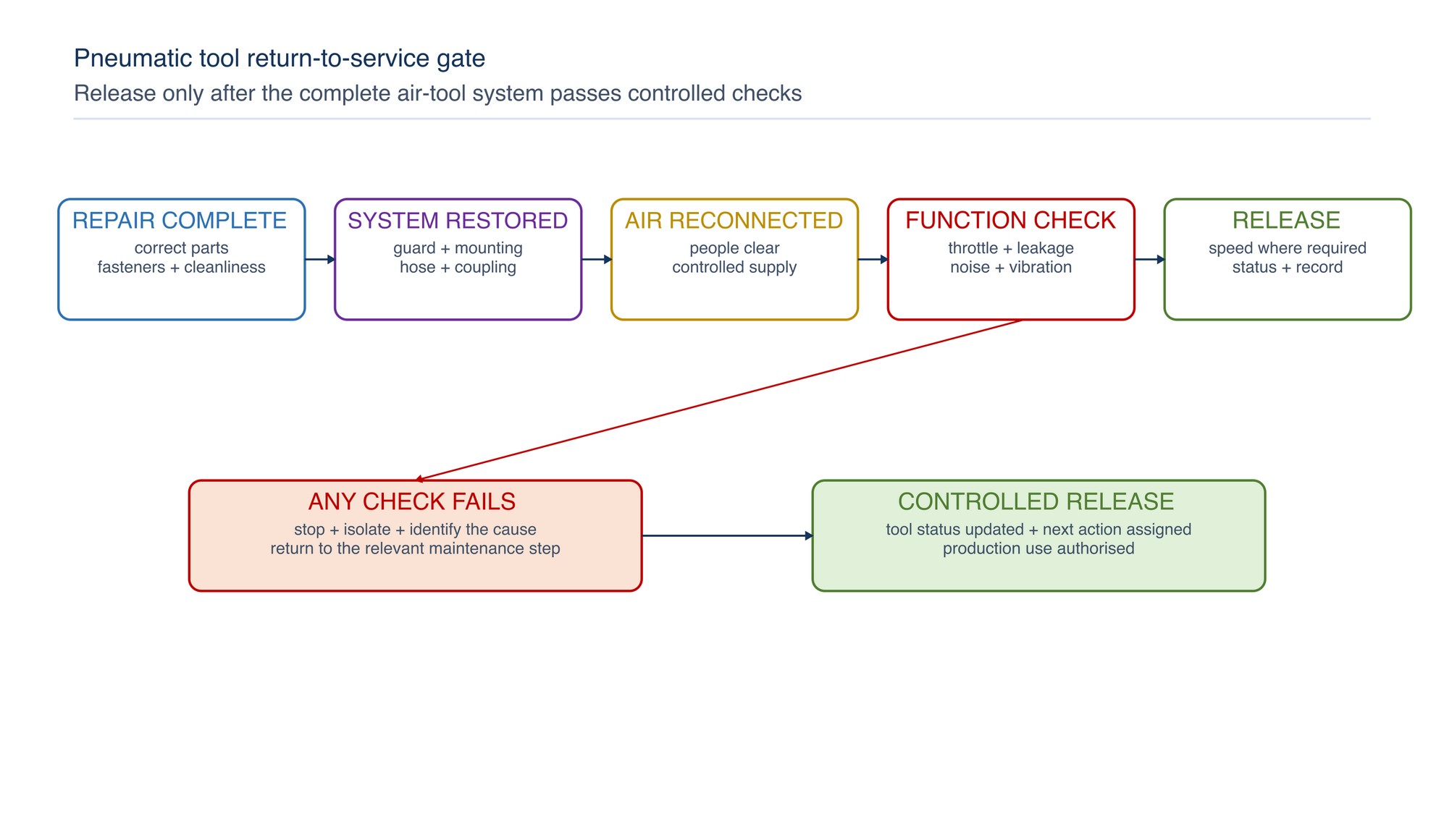
Use this release sequence:
- confirm work and parts are complete;
- remove loose items and restore covers, guard, handle and exhaust components;
- confirm throttle-off condition before connection;
- connect the correct hose and coupling with required retention;
- pressurise gradually from a stable, controlled position;
- check leakage and throttle return;
- verify free speed where required;
- observe noise, vibration, heat and exhaust condition;
- isolate again before fitting the abrasive;
- confirm tool–accessory compatibility; and
- record release and next maintenance action.
Any abnormal result returns the tool to isolation and investigation.
Pneumatic tool maintenance checklist
- [ ] Tool identity, rated information and service instructions are confirmed.
- [ ] Air supply is isolated, pressure is bled and disconnection is verified.
- [ ] Hose, coupling, retainer and routing are serviceable.
- [ ] Filter, separator, drain, regulator and gauge are functioning.
- [ ] Air contamination and treatment match the tool and process needs.
- [ ] Correct lubrication method, product, point and quantity are used.
- [ ] Throttle, lock-off and shut-off return reliably without leakage.
- [ ] Governor or speed-control assembly remains correct and unmodified.
- [ ] Exhaust and silencing components are clear, secure and correctly directed.
- [ ] Spindle, flange, chuck, collet or mandrel is serviceable.
- [ ] Guard, handle, housing, labels and fasteners are complete.
- [ ] Internal parts and passages are clean and correctly assembled.
- [ ] Required free-speed check uses a calibrated method and passes.
- [ ] Controlled connection and no-accessory functional test are satisfactory.
- [ ] Tool status, repair, parts, measurements and next action are recorded.