
Production engineers, process engineers, supervisors, technical buyers, QA/QC personnel, maintenance teams, storekeepers, contractors and abrasive users
Application definition; workpiece and outcome requirements; abrasive form and dimensions; grading systems; machine and interface compatibility; wet or dry use; safety information; inspection and acceptance; supplier alternatives; substitutions; revision control; worked specification examples and troubleshooting.
The product must carry legible identification and be supplied with the information needed for safe selection, storage, mounting and use. FEPA provides separate safety-instruction routes for bonded, coated and superabrasive products, reinforcing the need to match the instructions to the product family. Never request removal of a safety marking, alteration of a wheel, use without the specified guard, or operation above the lower permitted speed of the machine/product combination. [S352]
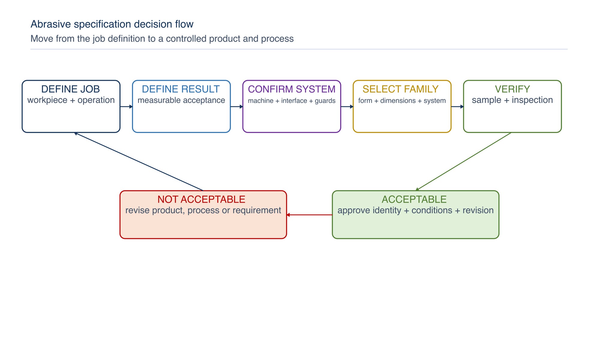
Specify the job, the result and the operating envelope before naming an abrasive. A complete specification allows the supplier, buyer, user and inspector to understand the same requirement.
Chapter objectives
After this chapter, the reader should be able to:
- distinguish an application specification from a product ordering description;
- define the workpiece, operation and measurable result;
- identify abrasive form, dimensions and mounting details without ambiguity;
- keep coated-abrasive, bonded-abrasive and superabrasive grading systems separate;
- state machine, speed-compatibility, extraction and wet/dry conditions correctly;
- distinguish mandatory requirements from preferences and supplier proposals;
- write a practical inspection and acceptance plan;
- compare alternative offers on a common technical basis; and
- control substitutions and revisions after approval.
An industrial abrasive specification should do more than repeat a grit number. It should identify what is being processed, what result is needed, which machine and mounting system will be used, how the product will be accepted and how changes will be controlled. Clear specifications reduce unsuitable quotations, uncontrolled substitutions, receiving disputes, wasted trials and process variation.
This chapter provides a practical method for writing enquiries, purchase descriptions and application specifications. It does not replace the product label, Technical Data Sheet, machine instructions, drawing, process qualification or workplace risk assessment.
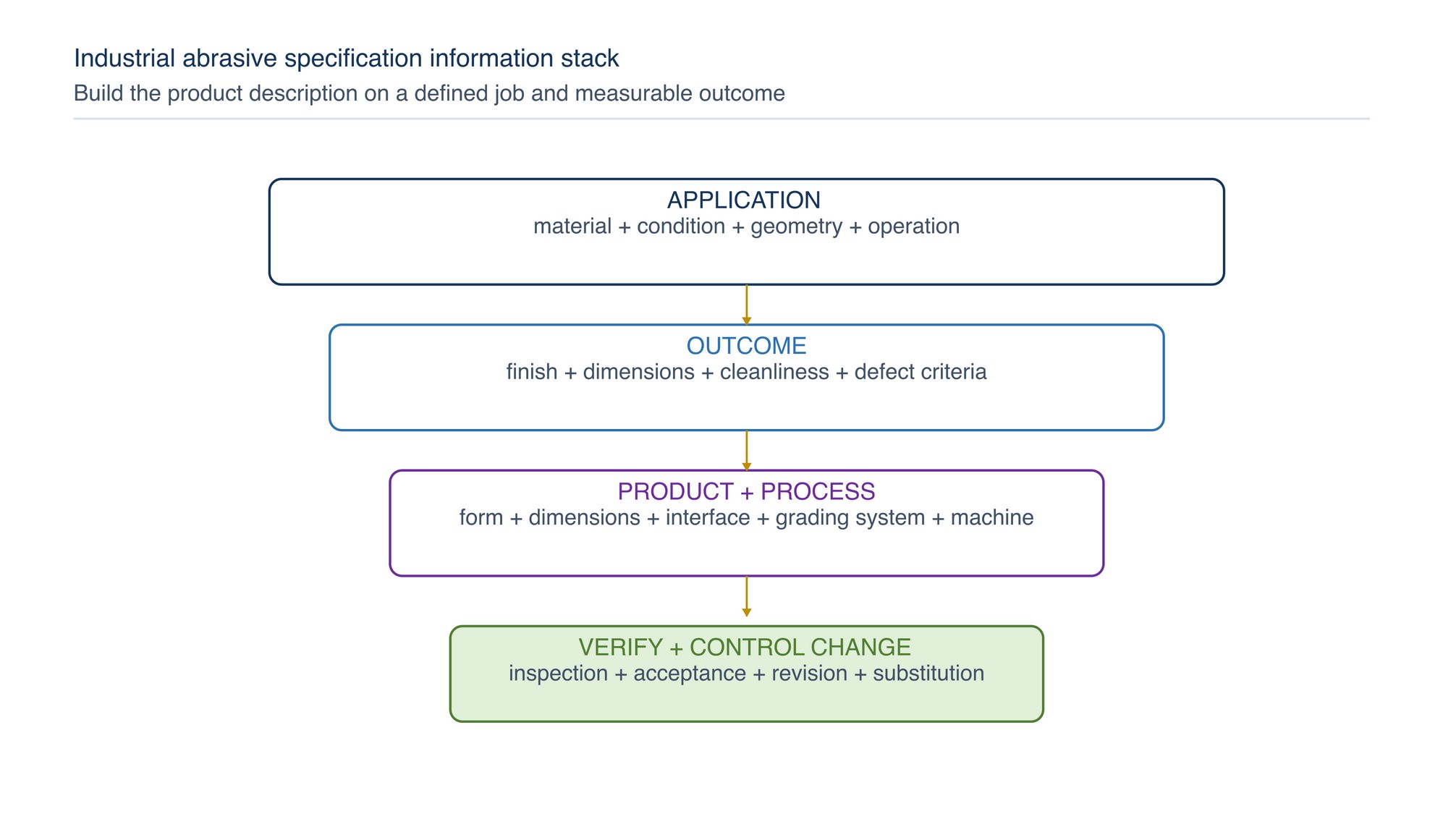
Use a three-layer specification
A useful industrial specification has three connected layers.
| Layer | Main question | Typical content |
|---|---|---|
| Application | What work must be done? | Material, condition, geometry, operation, access, allowance, batch pattern |
| Outcome | What constitutes an acceptable result? | Surface texture, dimensions, edge condition, cleanliness, defect limits, appearance, inspection method |
| Product and process | What product and operating envelope will deliver the result safely? | Abrasive form, size, mounting, grain system, machine, wet/dry use, controls, traceability |
Do not begin with a copied product code unless the exact controlled product is already approved. A code without the application and acceptance basis makes alternatives difficult to assess and can conceal a change in dimensions, construction, backing, bond, mounting or intended use.
State the purpose in one sentence
Start with a short duty statement that a technical supplier can understand. A good statement identifies the operation, workpiece and required result without prescribing an unverified solution.
Example: “Blend welded stainless-steel fabrications to a uniform directional finish while preserving drawing dimensions and preventing cross-contamination.”
This is more useful than “supply fine sanding discs” because it identifies the process purpose. The remainder of the specification then defines what “uniform”, “preserving” and “preventing” mean for the job.
Define the workpiece
The same abrasive can behave differently on different alloys, hardness levels, coatings, heat-treatment conditions and geometries. Record the workpiece in practical terms.
| Workpiece field | What to state | Why it matters |
|---|---|---|
| Material | Grade or controlled material description | Guides grain, bond and contamination decisions |
| Condition | Cast, forged, rolled, welded, heat treated, coated or previously finished | Influences scale, hardness, loading and heat response |
| Geometry | Flat, edge, radius, bore, tube, profile or complex fabrication | Determines access, contact area and product form |
| Thickness and stability | Thin sheet, heavy section, supported or flexible feature | Influences distortion, heat and pressure sensitivity |
| Surface condition | Scale, weld reinforcement, burr, coating, corrosion, scratch or existing finish | Defines the starting state and removal duty |
| Allowance | Material available for removal | Prevents over-processing and dimensional loss |
| Sensitive features | Datum, edge, coating boundary, thread, seal face or cosmetic face | Directs protection and inspection |
| Cleanliness restrictions | Dedicated stainless, non-ferrous, food-contact or coating-preparation controls | Prevents unacceptable contamination |
Where several workpiece conditions occur, define the worst credible case or create separate specification lines. Do not assume that one process setting will cover a light blend and heavy stock removal equally well.
Define the operation before the product
Use an operation name that describes the intended material-removal or finishing task.
| Operation | Primary purpose | Important specification points |
|---|---|---|
| Cutting-off | Separate material along a path | Material, section, cut access, cut quality, machine and wheel geometry |
| Heavy grinding | Remove weld, gate, scale or stock | Removal volume, contact area, geometry preservation and heat sensitivity |
| Deburring | Remove sharp or loose edge material | Edge profile, burr type, access and acceptable edge break |
| Blending | Smooth transitions without excessive stock loss | Starting defect, surrounding finish and contour control |
| Surface preparation | Create a clean, suitably textured surface for the next process | Contaminant condition, coating system and cleanliness/texture criterion |
| Finishing | Produce a defined texture or appearance | Direction, uniformity, parameter, sampling and visual reference |
| Polishing | Reduce visible texture or produce a specified appearance | Previous steps, compound system, cleanliness and inspection lighting |
Avoid using “polishing”, “sanding” or “grinding” as interchangeable terms. They describe different duties and may lead suppliers toward different product constructions.
Convert “good finish” into an acceptance requirement
Terms such as smooth, bright, fine, clean or scratch-free are too subjective unless supported by an inspection method or reference standard. Choose criteria that match the functional risk.
| Result category | Possible requirement | Verification approach |
|---|---|---|
| Surface texture | Drawing-defined profile parameter and limit | Controlled instrument, stated measurement direction, locations and settings |
| Dimensional integrity | Drawing tolerance or maximum stock-removal allowance | Calibrated dimensional measurement at defined features |
| Edge condition | Burr removed; defined edge form maintained | Visual and tactile inspection plus dimensional check where critical |
| Appearance | Approved reference panel and viewing conditions and direction | Side-by-side comparison under controlled lighting |
| Cleanliness | No visible residue; process-specific cleanliness requirement | Defined visual, wipe, water-break or other approved method |
| Defects | Limits for gouges, chatter, burn, heat tint, pull-out or exposed substrate | Defined inspection area, lighting, magnification and acceptance rule |
| Coating preparation | Coating-system requirement for cleanliness and profile | Applicable coating specification and approved measurement method |
ISO 21920-1 provides the current framework for indicating profile surface texture in technical documentation; ISO 21920-2 defines terms and parameters; ISO 21920-3 addresses specification operators. Use the applicable controlled drawing standard and measurement procedure rather than copying an isolated roughness value. [S343; S344; S345]
Specify the measurement location, direction, sample quantity, instrument settings and decision rule. A surface can give different readings across and along a grinding pattern. An average value can also hide a local gouge or edge defect.
Identify the machine and interface
The abrasive must be compatible with the actual equipment and mounting arrangement. Record:
- machine or tool type;
- manufacturer, model and identification where relevant;
- spindle, arbor, thread, flange, backing pad, contact wheel or quick-change interface;
- available guards and required product geometry;
- machine speed range or controlled operating setting;
- power source and available power;
- contact-wheel or backing-pad hardness and profile where relevant;
- wet, damp or dry operating condition;
- extraction or coolant arrangement; and
- access, orientation and workholding constraints.
Do not select an abrasive solely because its nominal diameter fits. Hole size, mounting system, flange arrangement, product shape, guard, machine speed and intended use must all be compatible.
When an exact product speed, dimension, mounting requirement, backing-pad compatibility or ordering code is required, Refer to the product label, Technical Data Sheet, or MKTECH representative.
Name the abrasive form precisely
State the physical form before the grain description.
| Product family | Useful identity fields |
|---|---|
| Bonded wheel | Type/shape, outside diameter, thickness, bore, specification marking, intended operation |
| Cutting wheel | Flat or depressed-centre form, diameter, thickness, bore, intended material/use |
| Flap disc | Diameter, bore or thread, profile, flap construction, abrasive grade/system |
| Fibre disc | Diameter, centre-hole arrangement, abrasive grade/system, compatible backing pad |
| Hook-and-loop or adhesive disc | Diameter, hole pattern, attachment system, backing and abrasive grade/system |
| Abrasive belt | Width, length, joint type/direction where relevant, backing, abrasive grade/system |
| Sheet or roll | Width, length, backing, perforation or cut form, abrasive grade/system |
| Non-woven product | Form, dimensions, attachment, density/grade designation and intended duty |
| Mounted point or wheel | Shape, head dimensions, shank dimensions, product marking and intended tool |
| Superabrasive wheel | Shape, dimensions, abrasive type, grain designation, concentration/bond information and mounting |
ISO 525:2020 covers bonded-abrasive shape types, dimensional symbols, specification, designation and marking, but it explicitly does not apply to coated or superabrasive products. Use the correct product-family framework. [S342]
Keep abrasive grading systems separate
A grit designation identifies a grain-size distribution within a stated system; it is not a complete product specification and does not guarantee a particular finish.
| Designation context | Product use | Specification practice |
|---|---|---|
| P-grade | Coated abrasives using the applicable ISO 6344 designation system | Write the P prefix and grade; do not omit the |
| F-grade | Bonded-abrasive grain designation using the applicable ISO 8486 framework | Write the F context when that controlled designation is intended |
| Superabrasive designation | Diamond or cubic-boron-nitride grain designation under the applicable system | State the system and product construction; do not reduce the product to grain size alone |
| Proprietary grade | Manufacturer-specific non-woven, structured, film or specialty product family | Use the exact controlled designation and product |
ISO 6344-2:2021 covers coated-abrasive macrogrits P12 to P220, while ISO 6344-3:2021 covers microgrits P240 to P5000. ISO 8486-1 provides the F-macrogrit context for bonded abrasives, and ISO 6106 covers checking and designation of diamond and cubic-boron-nitride grain sizes. [S346; S347; S348; S349]
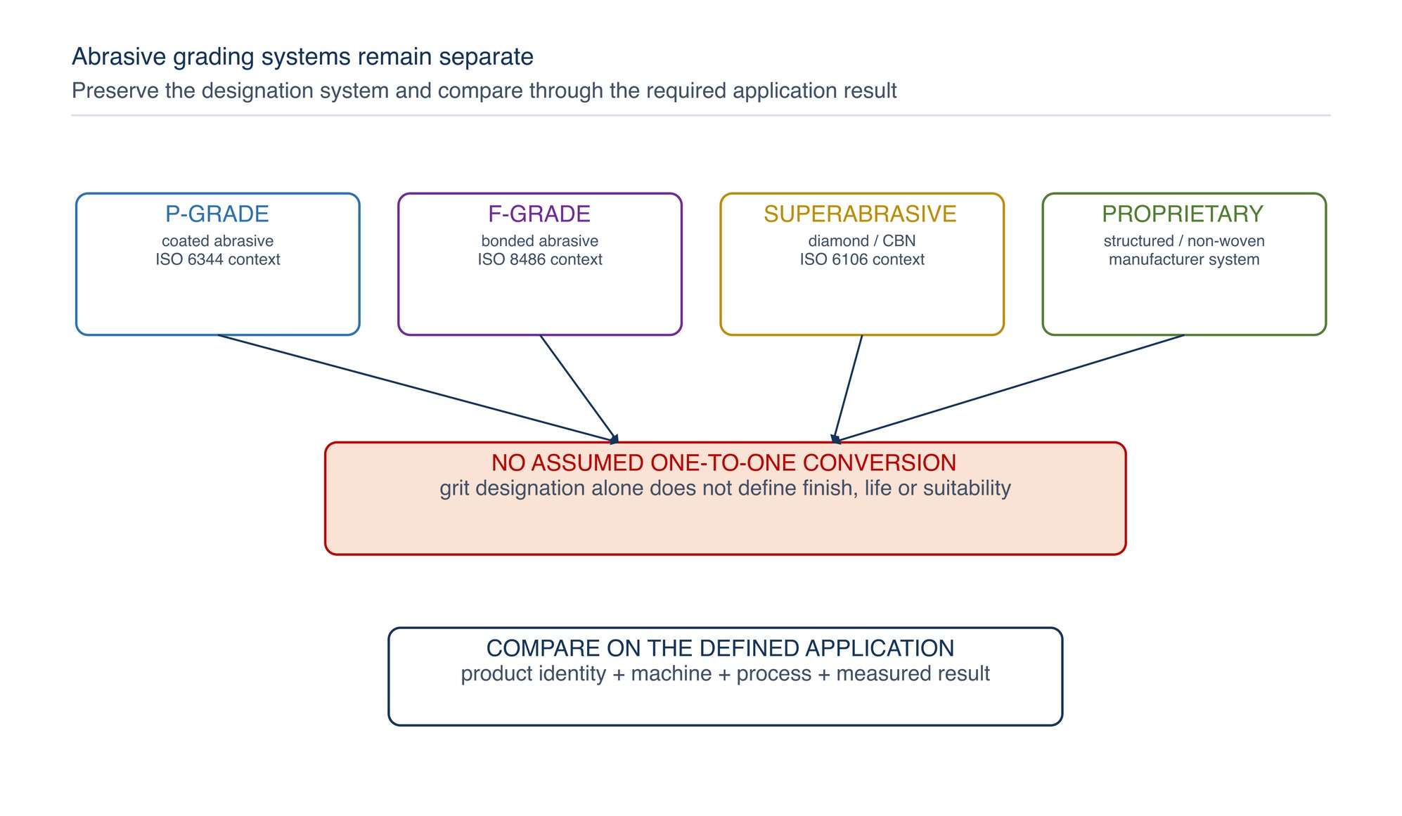
Grit, grain material, coating pattern, backing, bond, structure, product flexibility, contact pressure, speed, coolant, workpiece and previous process steps all influence the result. Two products carrying the same nominal grade can perform differently.
Specify attributes at the right level
Use three requirement classes to prevent over-specification.
| Requirement class | Meaning | Example treatment |
|---|---|---|
| Mandatory | Necessary for safety, fit, process or quality | Correct form, dimensions, interface, intended use and acceptance outcome |
| Preferred | Beneficial but open to an equivalent solution | Preferred backing flexibility, packaging quantity or product format |
| Supplier proposal | Best selected using supplier product knowledge | Grain technology, coating design, bond system or alternative sequence |
Over-specification can exclude a suitable product without improving the result. Under-specification can produce incomparable quotations. State proprietary construction details only when they are essential to an approved process or exact replacement.
Define the operating envelope
The specification should state the conditions within which the product will be evaluated and used:
- workpiece material and starting condition;
- machine and mounting arrangement;
- operation and contact geometry;
- wet or dry use;
- coolant or process-fluid identity where applicable;
- production pattern, such as intermittent repair or repeated batch work;
- thermal, contamination and appearance sensitivities;
- extraction and housekeeping controls;
- operator access and workholding; and
- approved sequence before and after the abrasive step.
Operating values should come from the actual product, machine, process qualification and risk assessment. Do not copy a speed, force, feed, pressure, pass count or coolant setting from a different product or application.
Write safety compatibility into the enquiry
Safety is not a separate purchasing note. Include enough information for the supplier to confirm intended-use compatibility:
- machine and tool type;
- product form and dimensions;
- mounting interface;
- intended operation and workpiece material;
- wet or dry condition;
- guarding constraints;
- hazardous-material or contamination concerns; and
- applicable workplace and customer restrictions.
The product must carry legible identification and be supplied with the information needed for safe selection, storage, mounting and use. FEPA provides separate safety-instruction routes for bonded, coated and superabrasive products, reinforcing the need to match the instructions to the product family. [S352]
Never request removal of a safety marking, alteration of a wheel, use without the specified guard, or operation above the lower permitted speed of the machine/product combination.
Define receiving and acceptance checks
Acceptance should confirm identity and condition, not attempt to recreate the manufacturer's product testing.
| Check stage | Practical checks |
|---|---|
| Documentation | Purchase description, product identity, revision, quantity and agreed certificates or data |
| Marking | Product designation, dimensions, intended use, traceability and safety information as applicable |
| Physical condition | Packaging damage, moisture, deformation, cracks, edge damage, contamination or illegibility |
| Fit | Dimensions and interface against the approved machine/accessory arrangement |
| Application sample | Defined workpiece, operator/machine condition, sequence and acceptance method |
| Release | Authorised decision, approved identity, conditions and revision record |
A sample result is meaningful only when the starting condition, machine, setup, operator method and measurement approach are controlled. Record both acceptable and unacceptable outcomes using the same criteria.
Build a technically comparable enquiry
Use the following structure for a request for quotation or technical recommendation.
| Enquiry field | Customer entry |
|---|---|
| Application statement | Operation, workpiece and purpose |
| Material | Grade, hardness/condition and coating where relevant |
| Geometry | Part form, access, thickness, edge and sensitive features |
| Starting condition | Scale, weld, burr, coating, scratches or prior finish |
| Required outcome | Drawing, texture, dimensional, cleanliness and appearance criteria |
| Machine | Type, model, interface, guard and available operating range |
| Product form | Wheel, disc, belt, sheet, roll, non-woven or mounted product |
| Dimensions | Outside size, width/thickness, bore, shank, belt length or attachment system |
| Use conditions | Wet/dry, extraction, coolant, production pattern and environment |
| Verification | Sample, measurement method, locations and acceptance rule |
| Commercial needs | Quantity, packaging, delivery, traceability and documentation |
| Alternative offers | Technical differences to be declared and separately identified |
Attach a drawing or clear photograph when geometry or access is difficult to describe. Mark the exact processing area and protect customer-sensitive information through the agreed document-control route.
Control supplier alternatives
Allow alternatives where they can improve availability, quality or cost, but require a clear comparison. The supplier should identify changes in:
- product family and intended use;
- dimensions or mounting;
- abrasive/grading system;
- grain or construction;
- backing, bond, flexibility or density;
- safety or storage information;
- process sequence or operating envelope; and
- expected inspection or acceptance method.
An “equivalent” product is not approved merely because its size and grit appear similar. Evaluate the change against fit, intended use, process result, safety information, contamination risk, storage and repeatability.
Control revisions and substitutions
Assign the specification a unique title, number, revision, owner and effective date. Record which product identity and process condition were approved against which workpiece and acceptance method.
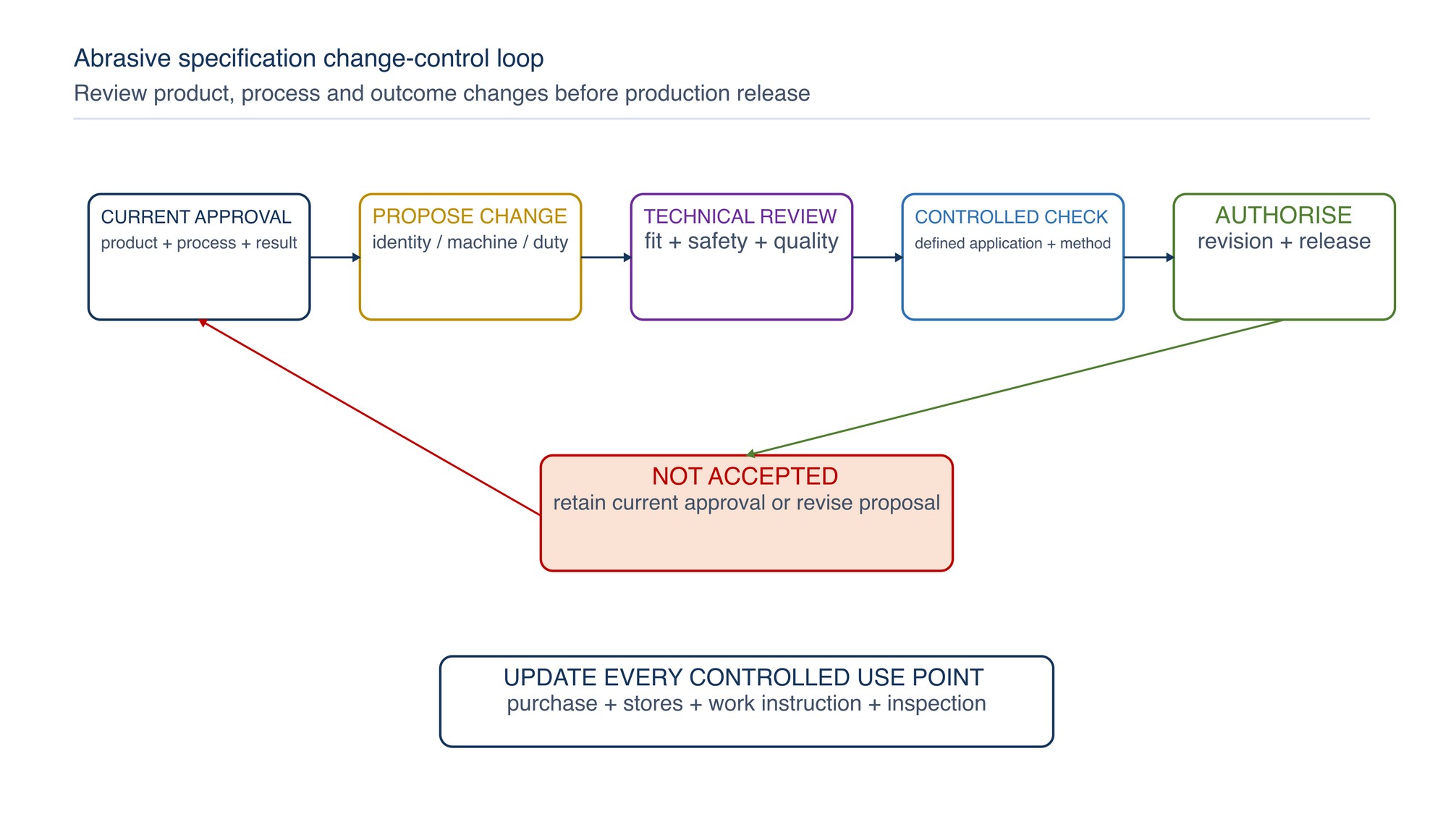
Changes that may require review include:
- manufacturer or product code;
- product form, dimensions or mounting;
- grading system or grade;
- backing, bond, density, structure or flexibility;
- machine, pad, contact wheel or guard;
- workpiece material or condition;
- wet/dry method, coolant or extraction;
- operating envelope;
- required result or measurement method; and
- packaging, storage or traceability arrangement.
Prevent superseded descriptions from remaining in purchase templates, store labels, work instructions or maintenance systems.
Worked specification patterns
16.1 Cutting-off application
Duty: Cut the identified alloy and section on the stated guarded machine.
Specify: workpiece material and section; cut access; flat or depressed-centre wheel form; dimensions and bore; intended operation; machine identity and speed compatibility; cut-quality criteria; burr and heat limits; sample and inspection method; marking and traceability.
Keep product-controlled: exact wheel designation, permitted speed, expiry/use-by information and mounting instructions.
16.2 Weld blending on stainless steel
Duty: Blend the weld transition to the approved contour and directional appearance without unacceptable heat tint, gouging or cross-contamination.
Specify: alloy; weld condition; surrounding thickness; contour; dedicated-product cleanliness; product form and attachment; machine and pad/contact system; required visual reference or texture criterion; protected features; inspection lighting and direction.
16.3 Coating preparation
Duty: Prepare the stated substrate for the named coating system.
Specify: substrate and existing condition; contaminant-removal stage; accessible geometry; coating-system cleanliness and texture requirement; abrasive family; extraction; inspection method; time and cleanliness controls before coating.
The abrasive description should not override the coating manufacturer's preparation requirement.
16.4 Production belt finishing
Duty: Produce the approved texture on a repeated component using the identified belt machine.
Specify: material and prior operation; belt width, length and running direction; joint/interface needs; contact wheel or platen; grading system and starting product family; wet/dry method; reference panel or measured criterion; sampling plan; belt-change trigger and change control.
For exact product construction, storage, compatibility or ordering information, Refer to the product label, Technical Data Sheet, or MKTECH representative.
Troubleshooting the specification
| Problem | Likely specification weakness | Improvement |
|---|---|---|
| Quotations are not comparable | Application and mandatory fields are unclear | Issue one common enquiry table and require deviations to be declared |
| Product fits the diameter but not the machine | Interface, bore, pad, flange, guard or speed basis omitted | Record the complete machine and mounting arrangement |
| Finish varies between batches | Starting condition, sequence, operating envelope or acceptance method uncontrolled | Define the application sample and measurement conditions |
| “Same grit” gives a different result | Grading system or product construction treated as equivalent | State the system, product family and outcome requirement |
| Receiving cannot identify approved stock | Product identity, marking or revision not linked to the purchase line | Add controlled identity and traceability fields |
| Supplier proposes a potentially useful alternative | Specification prohibits all variation or lacks an evaluation path | Separate mandatory requirements from supplier proposals and use change control |
| Operators rely on catalogue claims | Workpiece and process conditions differ from the published example | Verify on the defined application and acceptance method |
| Surface passes roughness but looks unacceptable | Visual direction, local defects or reference appearance omitted | Combine measured and visual criteria where function requires both |
Specification review checklist
Before issue, confirm that the specification:
- identifies the operation, workpiece and starting condition;
- states the required result and how it will be checked;
- identifies the machine, interface, guard and use condition;
- names the abrasive form and dimensions clearly;
- states the grading system rather than an isolated number;
- separates mandatory, preferred and supplier-proposed features;
- includes documentation, marking, condition and traceability checks;
- defines how samples and alternatives will be evaluated;
- controls revisions, substitutions and superseded descriptions;
- contains no invented product value or performance guarantee; and
- directs exact product values to controlled product information.
Concise safety reminders
- Confirm product, machine, mounting and intended-use compatibility before purchase and use.
- Never infer a permitted operating speed from product appearance or size.
- Do not mix wheel, flange, pad, guard or attachment components unless the combination is permitted.
- Treat illegible, damaged, wet, distorted, contaminated or suspect products through the site's segregation process.
- Control dust, sparks, noise, vibration, coolant and workholding for the actual task.
- Follow the product label, Technical Data Sheet, machine instructions and workplace risk controls.
Technical RFQ Checklist
The Technical RFQ Checklist grid appears on the following page of the printed handbook, outside this chapter extract.